
Battery Packs
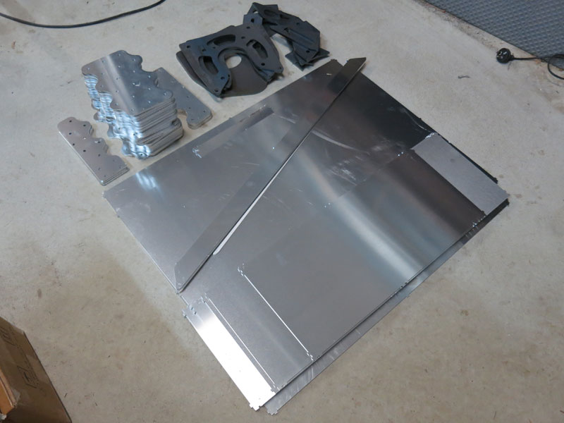
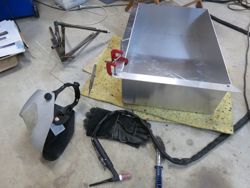
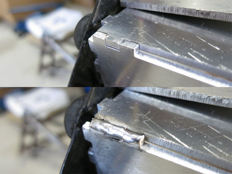
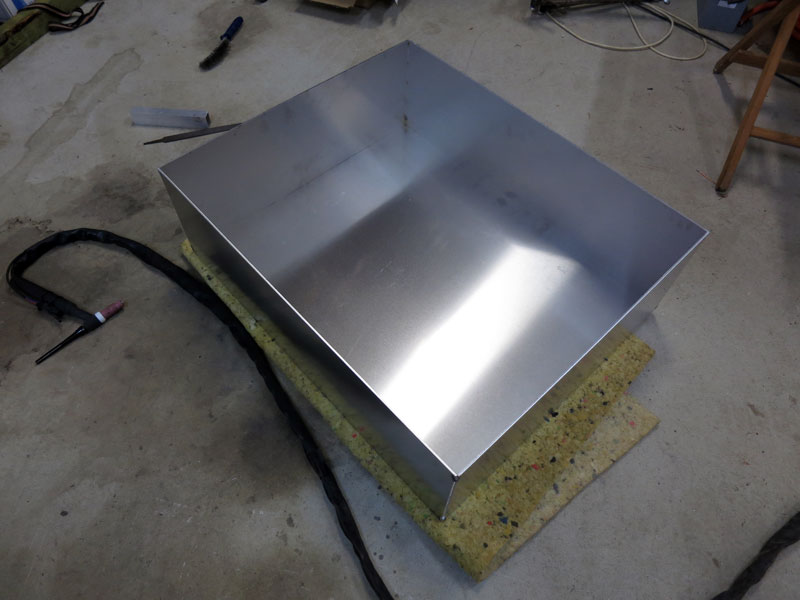
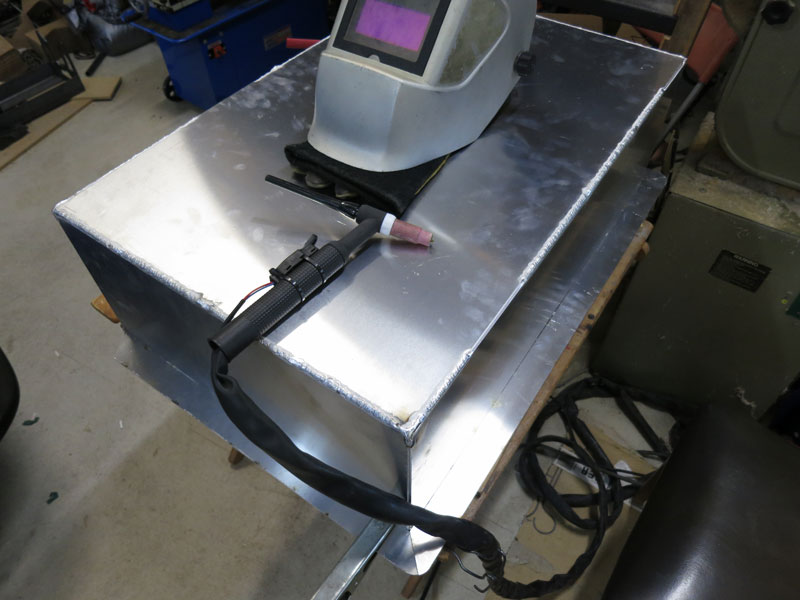
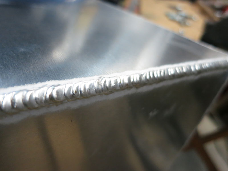
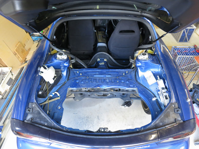
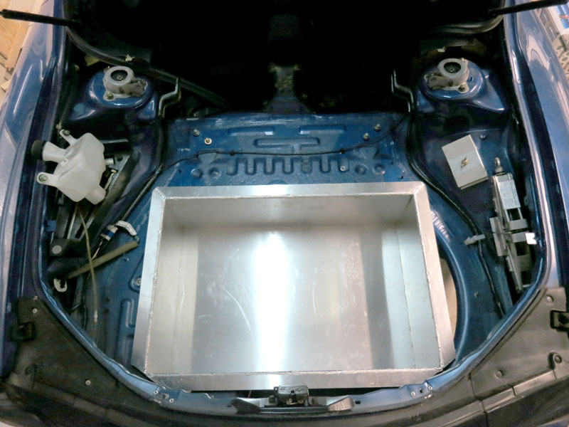
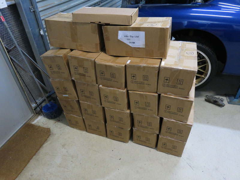
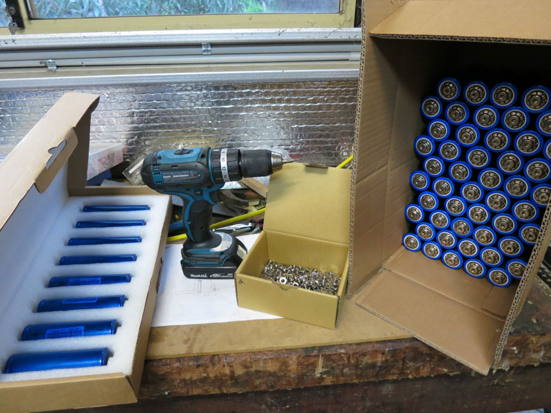
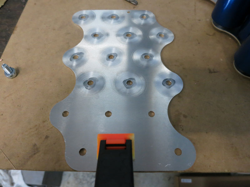
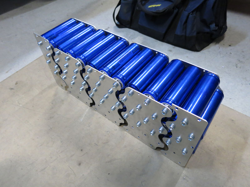
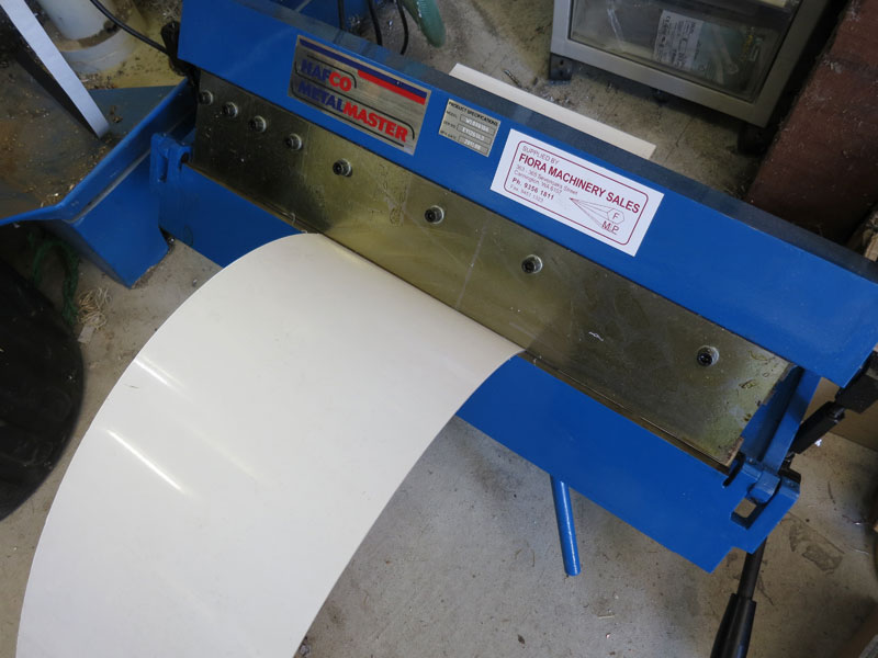
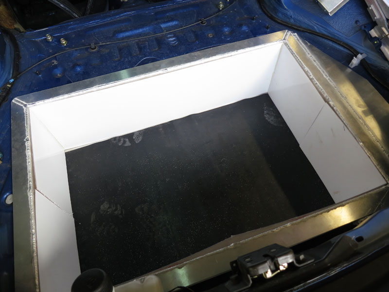
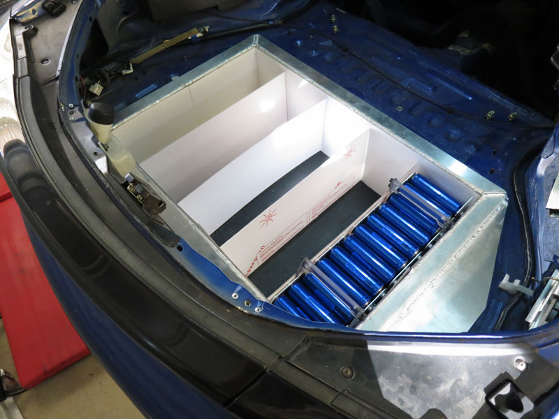
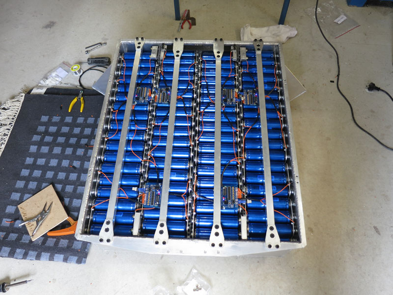
First step was putting the boxes together. As I did with the MX5, I got the laser cut parts with small jigsaw tabs at intervals, which makes it very easy to assemble the box. Then basically I just ran the TIG welder over the teeth to melt them together as a tack weld. Once the box was all tacked together, I proceeded with full the seam welding. Welding all the sides completely is quite time-consuming but gives a nice result, makes them totally weatherproof, and gives confidence that the box will never fall apart! The next thing I had to do was a little scary (for fear of irreparably ruining a beautiful and expensive car): cutting a big hole in the car boot to accommodate the rear battery box. The rear box isn't very deep but is quite wide and long, spanning most of the boot floor. In fact it's quite a tight fit. So I had to strip out most of the interior panels etc to clear out the area to be cut. After carefully measuring and marking the lines to be cut, I got to work with a 4" angle grinder and cutting disc. Basically the rear battery box goes where the fuel tank and spare wheel were - and the total weights are not dissimilar. Unfortunately I lose the spare wheel, but it's actually not a legal requirement to have one in your vehicle in Australia. (When did you last need yours?) Cell Array AssemblyAlthough the Headway cells offer superior performance to normal large format prismatic cells, their relatively small 10Ah size means you have to use hundreds of them in a normal EV-sized pack, so the extra time and effort to build a pack is significant! I'm starting off with 88S6P, which is actually 2/3rds of what I could fit in the vehicle (and indeed have designed the packs to accommodate). The smaller starting pack is mostly for cost and weight considerations. It should still manage around 100km maximum range with this pack, which is all I really need. But if/when I have a spare $5K down the track and want a bit more power and range, I can add the extra third later. In the meantime, I will have spacers beneath the arrays to fill out the extra volume. I was not particularly impressed with the M6x6 fixing hardware that came with the cells. With the spring washer, washer and interconnector added, there was only a few mm of thread engaging in the cell. The cell thread depths are actually about 10mm, so I decided to replace the orignal M6x6s with M6x12s, as well as using bigger spring washers for more tension. The cell interconnectors are aluminium, which is a very good conductor of electricity - not quite as good as copper, but much cheaper and lighter, so it can be a good choice in EV conversions. However, the aluminium oxide that quickly forms on its surface is a terrible conductor, so it is important to remove this before assembly. I use a small rotary wire brush in a cordless drill. I also add some Noalox to keep air and moisture out, which prevents the oxide from reforming over time. Then it's just a case of screwing all the interconnectors to the cells, taking care not to get polarities wrong or touch interconnectors together accidentally during assembly! To help move the arrays around, and for lifting them in/out of the battery boxes, I fabricated a couple of lift handles from polycarbonate which lock in to opposite screw heads (pictured below).
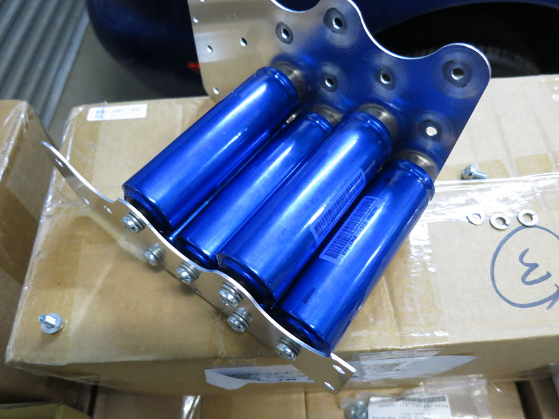
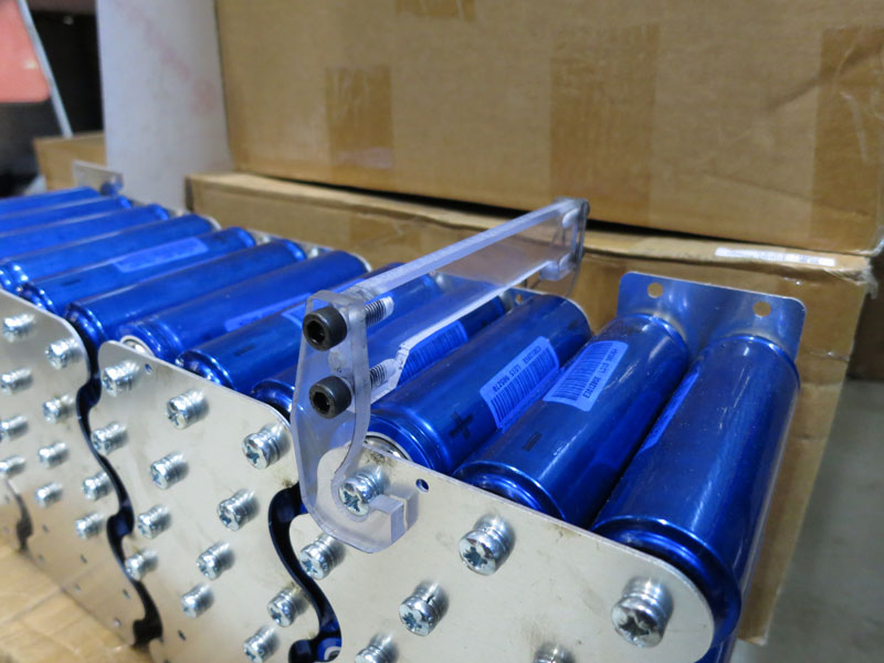
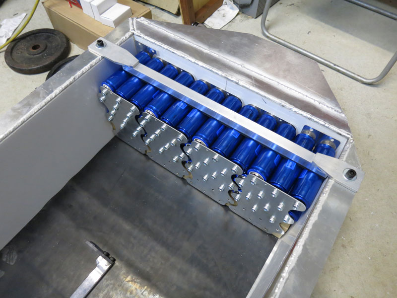
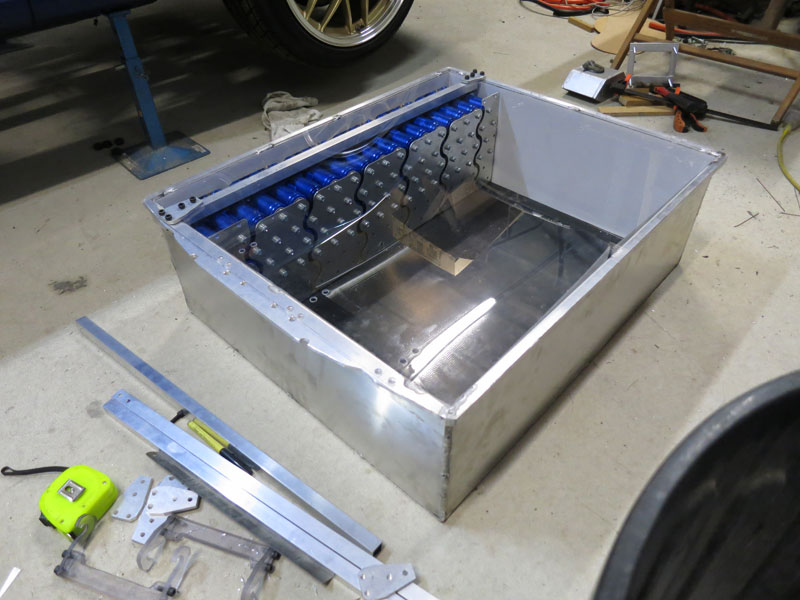
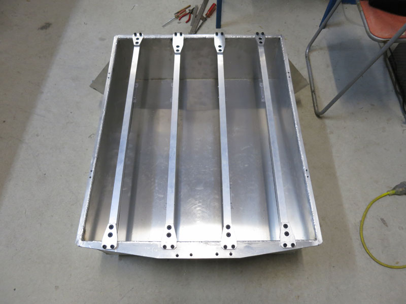
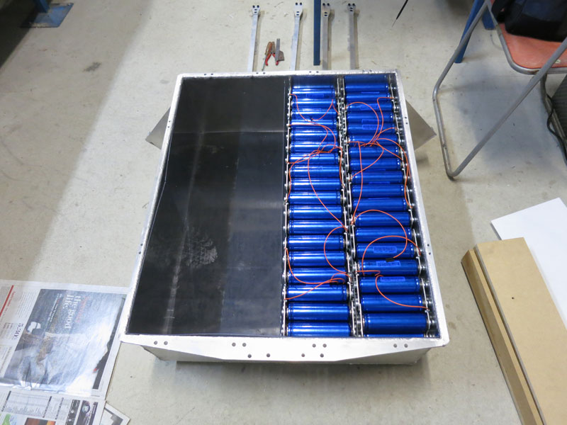
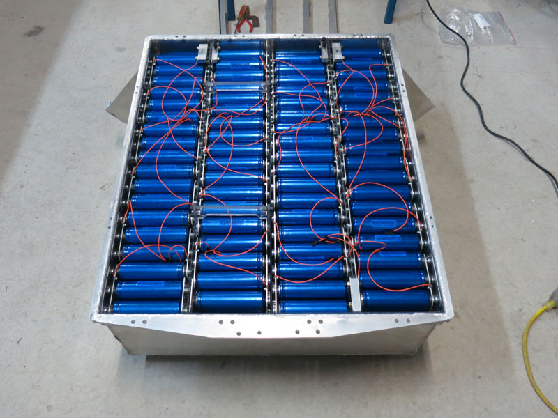
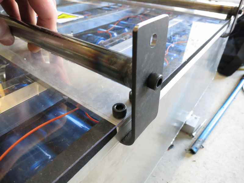
Rear Battery BoxThe battery boxes are made from aluminium, so of course need a lining of insulation between them and the cells. For this I used 1.5mm polycarbonate sheet. Polycarbonate is my favourite engineering plastic because it is very robust, good to machine, and looks attractive. It is also flame retardant, which is quite handy (in fact is a requirement under SAE regulations for battery enclosures - though not by law yet in Australia). To restrain the batteries in the boxes, I fabricated hold-down bars from 20x20mm aluminium tubing (from Capral) with 40x6mm mounting tabs welded on each end, and 18x6mm foam rubber (from Clark Rubber) on the underside. Below you can see a test fit of the first bar over a cell array in the rear battery box. I also prepared and attached BMS flyleads to each cell interconnector prior to installation, because they were going to be much to fiddly to attach in-situ!
Front battery box
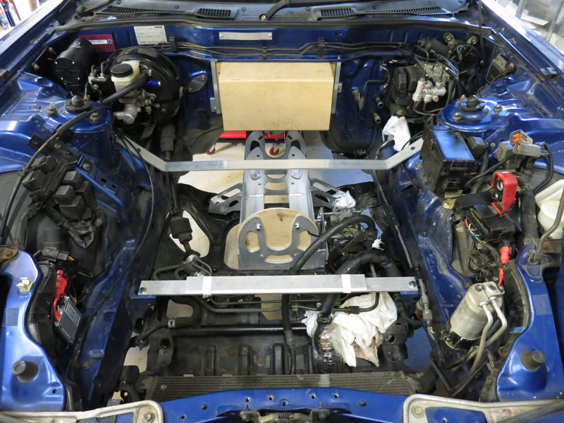
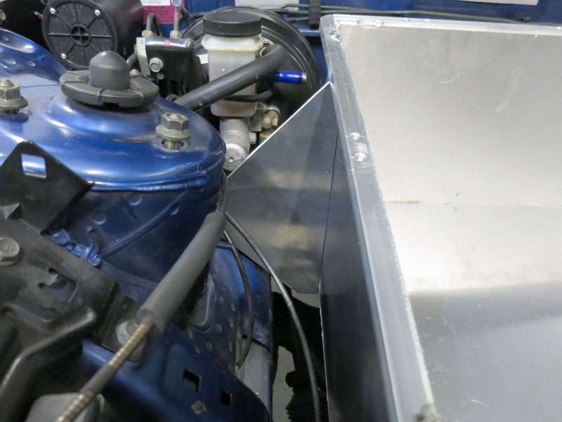
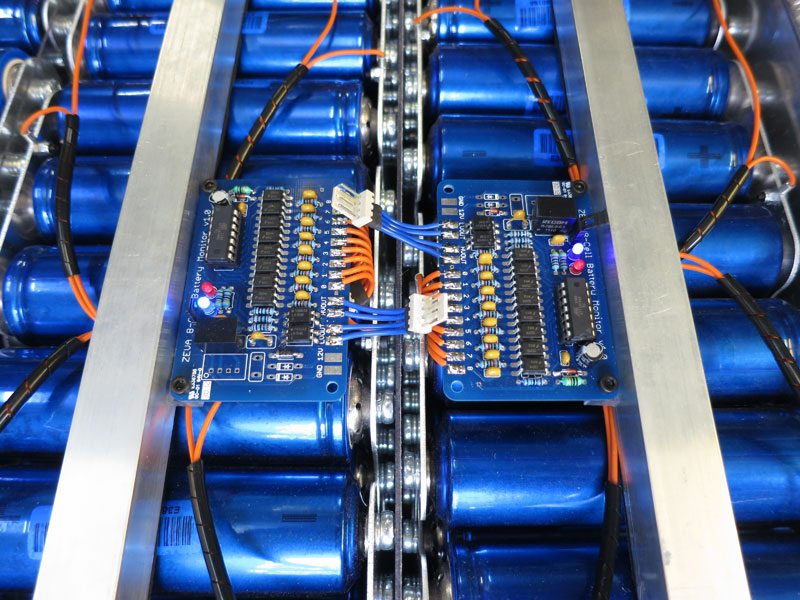
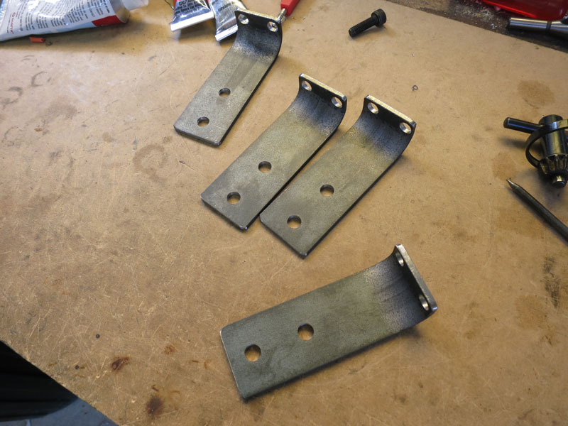
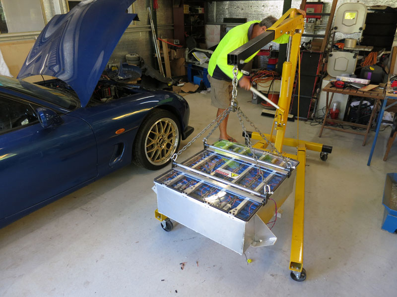
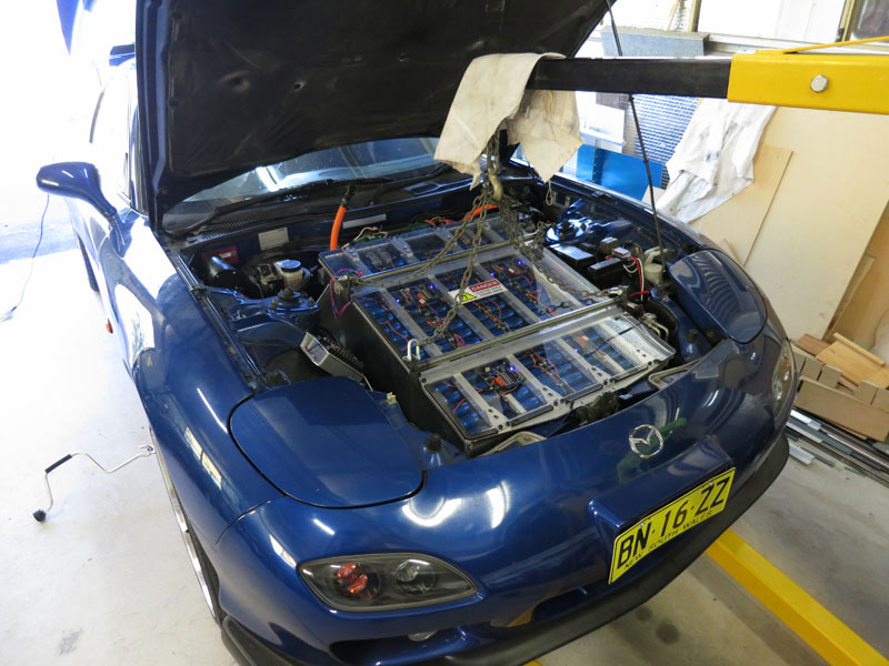
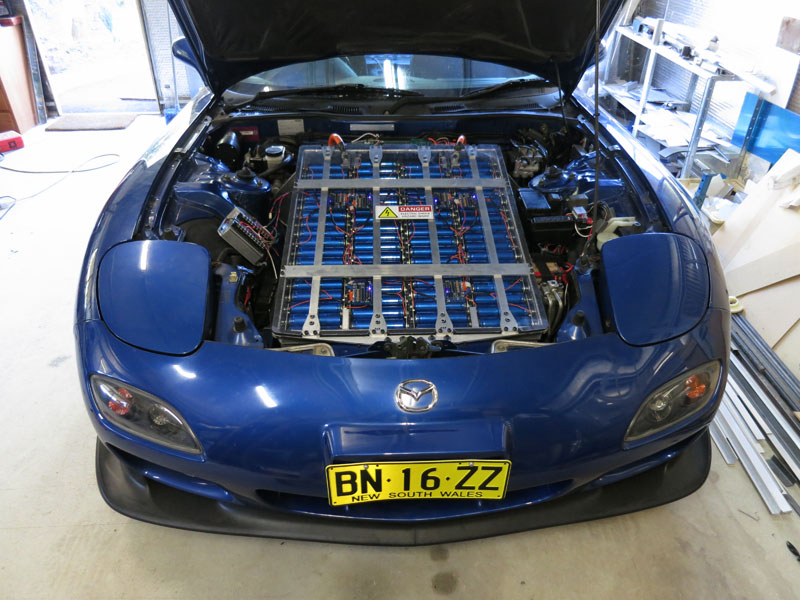
There are effectively 5 mounting locations for the front battery box in the engine bay, with a total of 10 bolts holding the box in place - four M6s across the top front, two M6s for a middle crossbar, and two M8s plus two M6s for a rear crossbar. Pictured below you can see the engine bay with the two aluminium crossbars which go under the battery box, later welded to its underside. (Note also my "WoodZilla", 1:1 mockup of the Zilla2K to verify clearance!) The front crossbar is 40x40x6 right angle aluminium, and attaches to two existing brackets between the chassis rails. The rear crossbar is 40x6 strap and attaches to some 45° surfaces just behind the suspension towers. For the rear crossbar I also added triangular gussetting which should help prevent skewing of the box under lateral load. The second and third pictures show attaching and test-fitting of these gussets. Once all the reinforcements were tack welded in place and I had verified that everything fit as it should, I completed the final welding of the front battery box. Then it was time to install the cells. The first picture below shows the hold-down bars which restrain the cells within the box. The cell arrays were assembled just like those in the rear pack, other than the slightly different arrangement (4x 12S6P instead of 5x 8S6P). The second photo below shows one of the four cell arrays for the front pack, with a the power supply on the right being used to charge all cells to 3.7V individually, so they are all "top balanced" before installation. Then the arrays were carefully lowered into the box - to my great relief, a snug fit without too much trouble getting them in! Once the cells were in, I fastened the hold-down bars then undertook the somewhat tedious task of wiring up all the BMS modules. You can also see a close-up of the BMS boards in the second picture below. (It's one of my own designs, an updated version of the earlier BMS design I wrote up recently.) Since it takes up most of the space in the engine bay and makes access to many other components difficult, the front battery box has been designed with four lifting points on the sides to allow me to lift it in and out of the engine bay when necessary. As such I assembled it out of the car, and installing it was one of the last steps in the whole project (e.g everything in the Electrical and Auxillaries sections were all complete before this happened, and I had test-driven the vehicle on just the rear pack). Below you can see pictures of the lift bars I made for the front box, and the careful process of lifting it into the engine bay with a crane with some assistance from my father - it was a two person job!
Continue reading --> Electrical Comments
|
||||||||||||||||||||||||||||||||||||||||||||||||||||||||||||||||||||||||||||||||||||||||||


Zero Emission Vehicles Australia © 2026 :: Terms and Conditions, Privacy Policy, Payments and Delivery, Warranty and Returns