
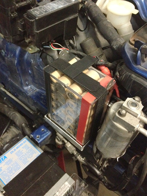
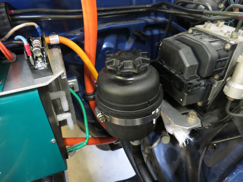
Auxiliaries12V BatteryMost vehicles use a lead acid battery for the 12V system, which weighs 10-20kg. In the interest of saving space and weight, I decided to replace the original battery with a lithium pack instead. (It is technically possible to go without a 12V battery entirely and just rely on the DC/DC converter, but in Australia it is actually a legal requirement to have a 12V battery which can independently run the hazard lights for at least 15 minutes. The battery is also good for load buffering, so the DC/DC doesn't see such a peaky load.) Most lead acid car batteries are about 50Ah capacity, but are not deep cycle. Replacing with lithiums (which are fine with deep cycling), you can get away with a much smaller capacity; I decided to go with about 20Ah. With a pile of K2 26650EV cells lying around from a cancelled project (and a battery spot welder handy), I decided to build a 4S6P pack giving 12.8V 19.2Ah, weighing about 2kg and taking up about 1L of space. I then enclosed the cells in a polycarbonate housing for a bit of weatherproofing. Side note: Although BMSs are generally recommended for any lithium batteries, with just four cells in series and if you "bottom balance" the cells, you can get away without a BMS entirely. The DC/DC converters which keep the 12V battery charged have a nominal voltage of 13.8V. Lithiums have a very flat voltage curve, so with just four cells at 13.8V total, the worst case scenario would be three cells at 3.2V (almost completely flat) and one at 4.2V (upper limit). But if the cells start balanced and have a reasonably similar capacity, they'll more likely always be within 0.1V of each other.
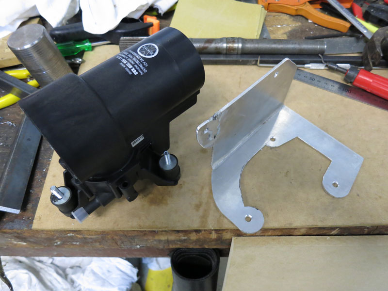
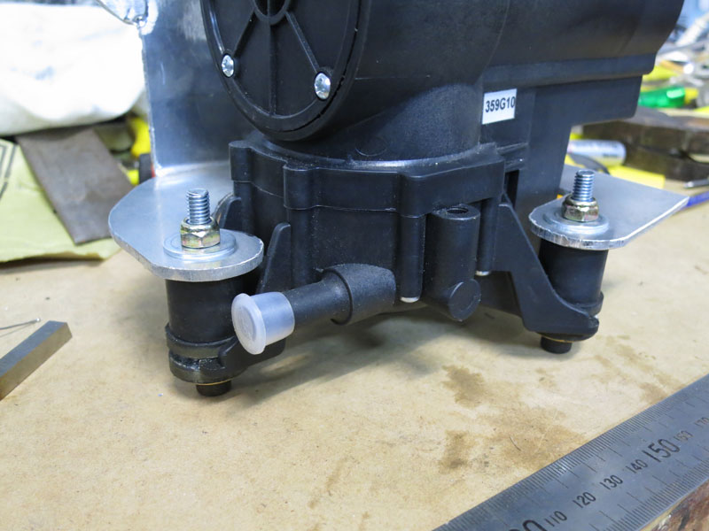
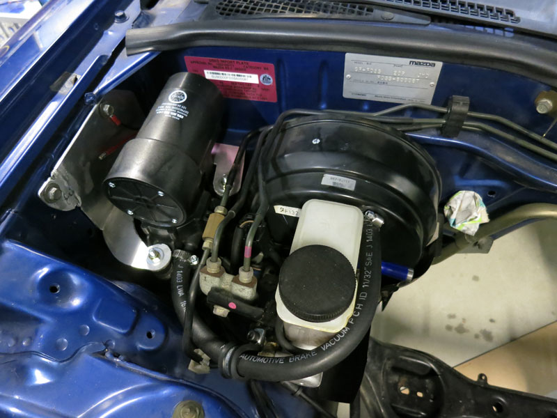
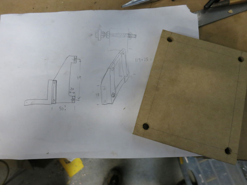
Brake vacuumAlmost all modern cars use vacuum-assisted brakes. In combustion engine-powered vehicles, there is a readily-available source of vacuum in the engine manifold, so they usually just have a vacuum hose from there to the brake master cylinder. In electric vehicles, there is no inherent vacuum available, so an electric vacuum pump is the usual solution. There are many options out there, my personal favourite is the Swiss-made MES 70/6E. Not the cheapest unit around, but it has nice "automotive grade" construction so it doesn't look out of place in an engine bay, and is very easy to install thanks to its compact size and built-in vacuum threshold switch. (With most pumps you need an external vacuum switch to stop the pump when it reaches ~20inHg. With this one it's just a single hose to the master cylinder, and ignition-switched 12V to the terminals.) My engine bay is going to be pretty full of motors and batteries, so I was glad to discover that the vacuum pump would fit in the corner next to the master cylinder. I fabricated an aluminium bracket to hold it in place, including some extra rubber vibration absorbers to help keep transmitted noise/vibration down.
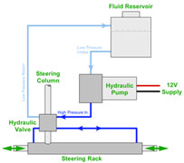
Power SteeringIf your donor vehicle has power steering, your EV conversion must either retain the functionality, or you can swap out the power steering rack for a non-assisted version with a higher ratio (if available). The S8 RX7s were never available without P/S (and it makes driving easier anyway) so I had to retain it. With a direct drive conversion you can't idle the traction motor at all times (which can allow you to run the OEM P/S pump off the traction motor), so my best option was to install an electric P/S pump.
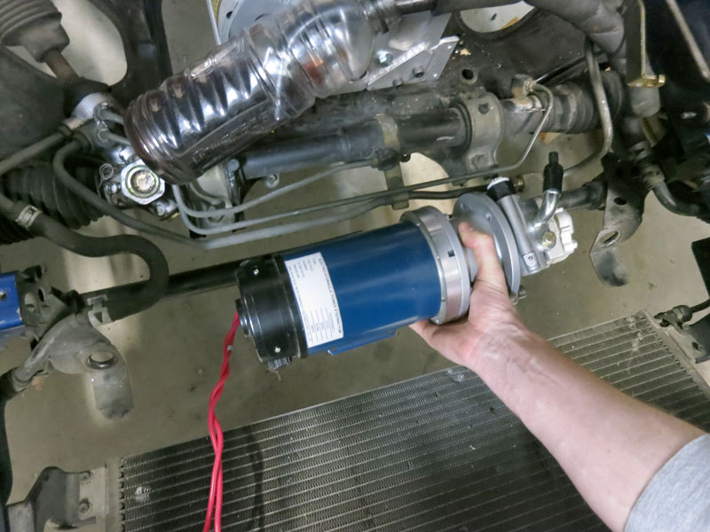
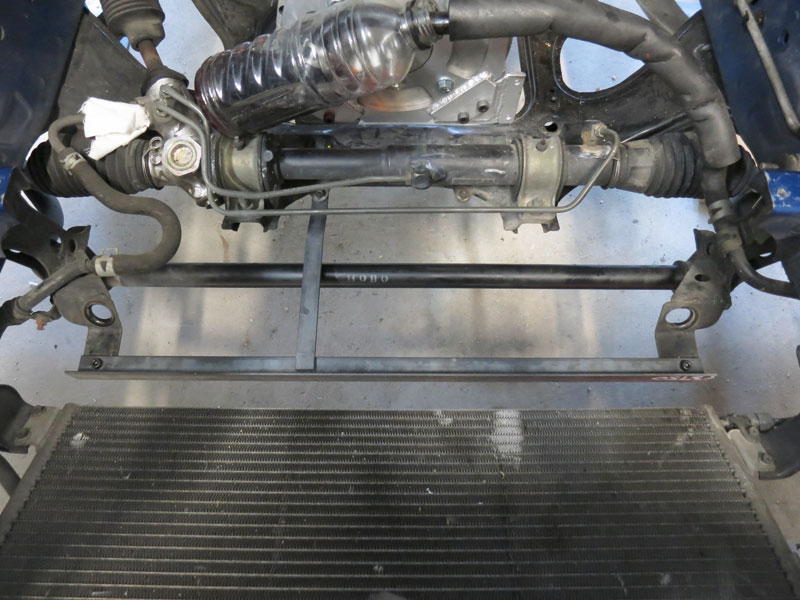
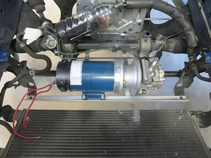
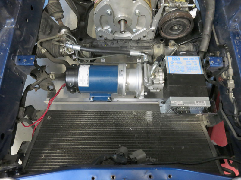
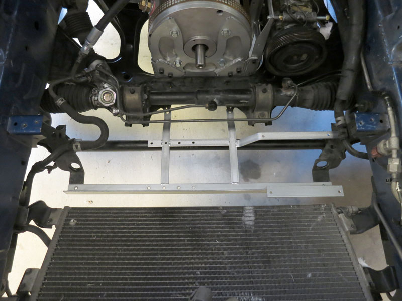
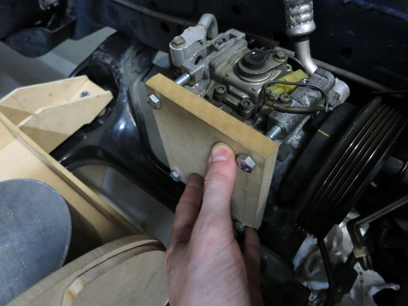
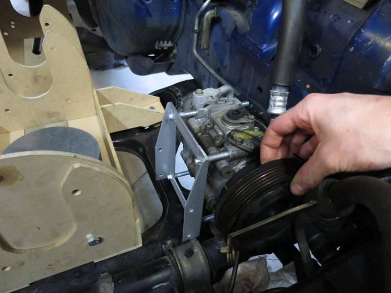
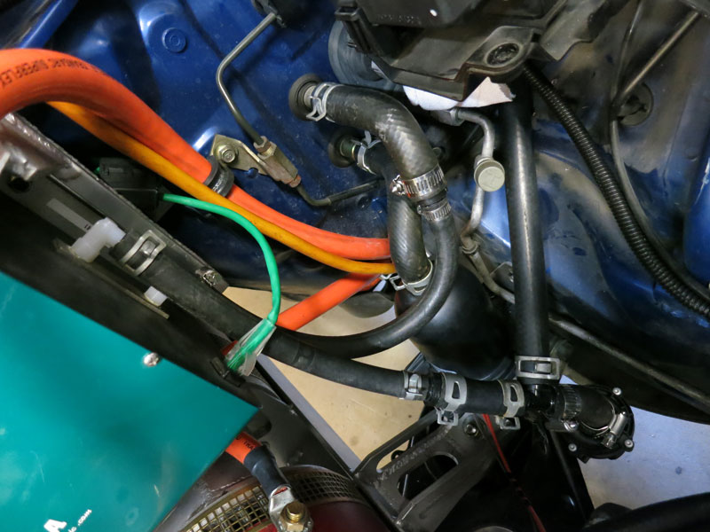
So I did a bit more research and came across a manufacturer in China who seem to simply couple a DC motor to an OEM vehicle P/S pump. The motor is bigger than I've seen on other electric P/S pumps which I suspected may be a sign it could spin slower and run quieter. Unlike the Mocen and Astra pumps, it has no built-in reservoir so may be slightly less convenient (more hoses etc), and the big motor makes it a fair bit heavier than most others out there, but I thought I'd give it a go anyway. In the first photo below you can see the pump in its proposed location, a convenient free space just in front of the steering rack. I then started fabrication of the frame from 3mm steel, attaching to four mounting points. Below you can see the (initially) completed bracket in-situ, and then the P/S pump installed. A little later I decided to install the DC/DC converter next to it and had to move the P/S pump about an inch to the left for them to fit side by side, as shown in the third picture. See the DC/DC Converter section below for more info about that. Also visible in the third photo below is the new high pressure hose between pump and steering rack. I had this made at Enzed. It was not cheap (about $100) but I guess that's "par for the course" with custom hydraulic hoses.
Since power steering is only important at low speeds, ultimately I hope to install a variable speed controller for the pump which reduces the assistance as driving speed increases, so it's not wasting so much power all the time. Running noise of this pump was reasonable - qualitatively, quieter than the Mocen or MR2 pumps, but probably louder than the Astra pump. After the first test drive, it seemed like the pump was handling the load just fine (no noticeable deficit in power assistance). So it seems like the pump will do the job. However due to the power draw, size/weight and noise, I'd say there are better options for P/S pumps out there.
DC/DC ConverterAll road-going vehicles have a (usually 12V) electrical system powering things like headlights, indicators, wipers, cabin electronics, etc. All of this must be retained after conversion, so you need a way of supplying power to it. In petrol vehicles, an alternator (generator) runs off the engine. Some electric vehicles retain the alternator and run it off the traction motor, but to me this is an inelegant solution (HV battery -> motor -> generator -> aux battery). For me, the best option is using a DC/DC converter, which steps down the voltage from the HV battery to keep the 12V battery charged. I'm using an IOTA DLS-55 HV, which is actually intended to run off 220-240 VAC but also works fine from a DC supply between about 200-360V. The IOTA converters have been very popular with EV conversions over the years because they are affordable and reliable. Unfortunately in 2011 IOTA revised the design, and the new version apparently no longer works off a DC supply. Due to the cramped engine bay, I was having some trouble finding a good spot to put the DC/DC converter. The IOTAs are not a sealed unit, so they are vulnerable to weather damage and it is best to install them somewhere protected from the elements. Unfortunately I didn't have any such locations big enough in the engine bay! So as mentioned previously, I ended up putting it next to the power steering pump. For a little weather protection I taped up the side and top vents (which help with natural convection, but the cooling fan will pull air through the case as needed), and added a splash guard across the front of the case. I don't think it's an ideal solution because it is a bit exposed to the elements, but I'll see how it goes. If it dies, I'll try to find a weatherproof DC/DC instead. In case you missed it, you can see the DC/DC converter and P/S pump mounted side by side in the pic at the end of the Power Steering section.
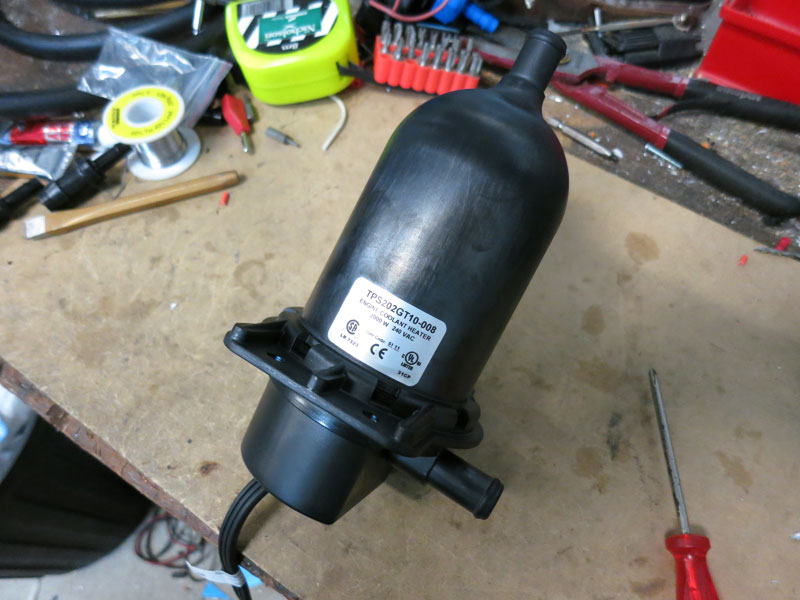
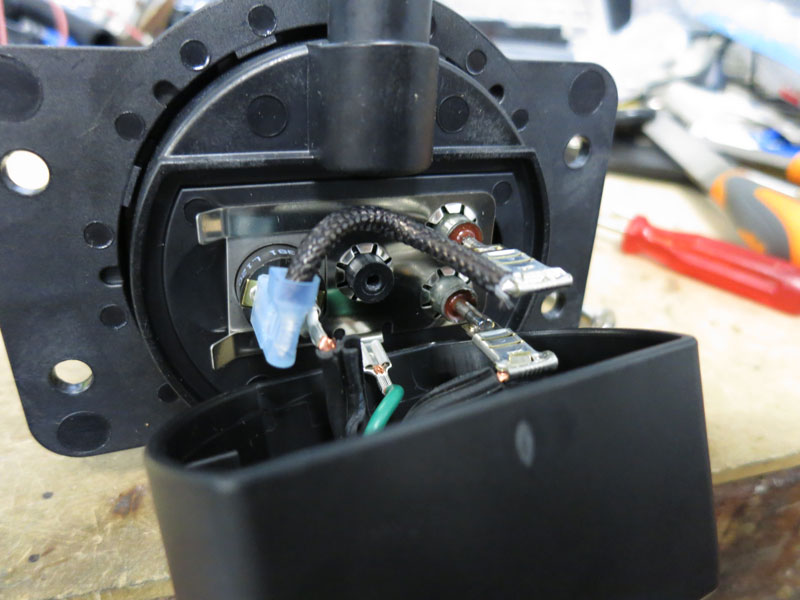
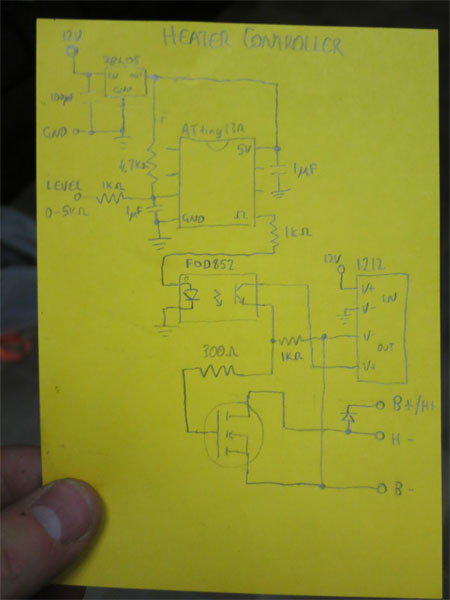
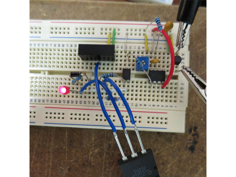
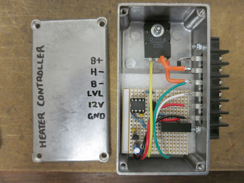
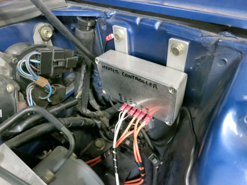
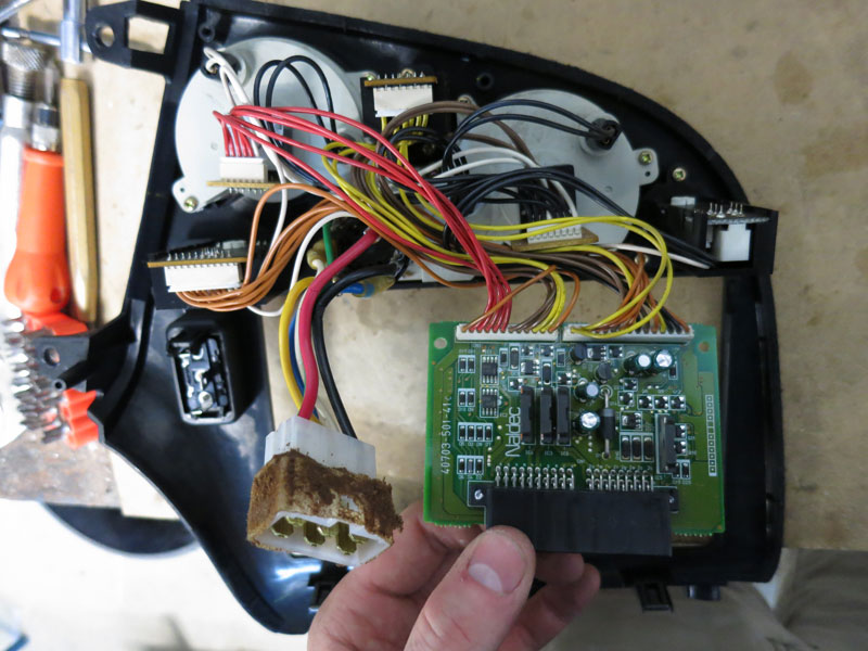
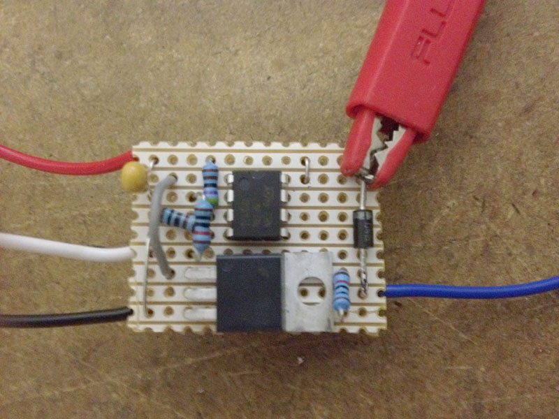
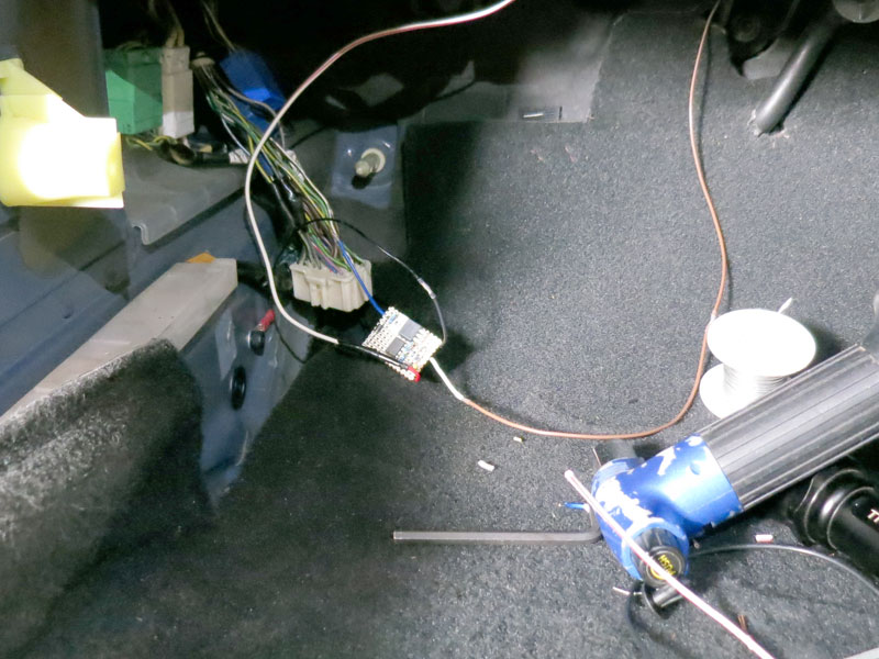
HeatingAustralia is a warm country and for most of the year we don't need to use our car heaters for comfort. However by law, all cars must have a source of heat for the purpose of demisting the front windscreen. In vehicles with an engine, the water cooling from the engine is run through a heat exchange in the vehicle dash to heat air entering the cabin. But similar to the brake vacuum problem, EVs don't have a readily-available source of heat, so some new heat system must be added. The three most common solutions, in ascending order of cost/complexity, are a ceramic heating element replacing the heat box in the dash, creating a new hot water circuit with a dedicated water heater and pump, or implementing reverse cycle air-conditioning. Reverse cycle A/C is the most efficient solution since heat pumps use about four times less energy to make heat, and it would have been my preferred solution, until I made some enquiries about the cost of getting it done and the possible complications with reversing the high and low pressure side in a system not designed for it. The Zilla controllers themselves require a water cooling circuit, and a friend of mine (thanks Malcolm) suggested the novel solution of using the Zilla's water cooling circuit for cabin heating. But being skeptical that the controller would produce enough heat for the task, I also decided to include a 2000W HotStart tank heater in the water circuit. The HotStart tanks won't heat the water above 50degC so shouldn't cause any overheating issues with the Zilla. (See the Water Cooling section for more information about the water circuit the HotStart is installed.) One important point to note with the HotStart heaters is that they are designed to work off AC power, and the internal thermostat is not rated for interrupting DC current. So they need to be re-wired, and use the thermostat to trigger a DC-rated switch. The HotStart tank I'm using is rated for 2000W at 240VAC. My pack is closer to 300V (DC), which I calculated would result in about 3000W of heat! To avoid possibly damaging the heater, I decided I would need to add a device which PWM'ed the heater so it only saw 2000W average. The device uses a small microcontroller to switch a large high voltage MOSFET at about 20Hz, with opto-isolation to keep the 12V and HV circuits separate. It's a bit like a cross between a big solid state relay and a small motor controller. A trivial addition was then to allow adjustment of the PWM duty cycle for variable amount of heating. The photos below summarise the development process. The last two pictures show the insides of the control panel for the fan/heat/aircon system, which had a scary number of wires and complicated control board! I avoided trying to reverse engineering or modify any of this, instead just swapping in my own potentiometer for the heat knob, plus new wiring going to my heater controller. The black taped-up device is the old heat mix adjuster (which is permanently set at "full heat" so air comes through the heat exchanger in the dash, which is now heated on command). Although it wasn't the most trivial solution, I'm a big fan of keeping the driving experience as intuitive as possible and reusing as much the original instrumentation as possible. It's the difference between a good EV conversion and a great EV conversion!
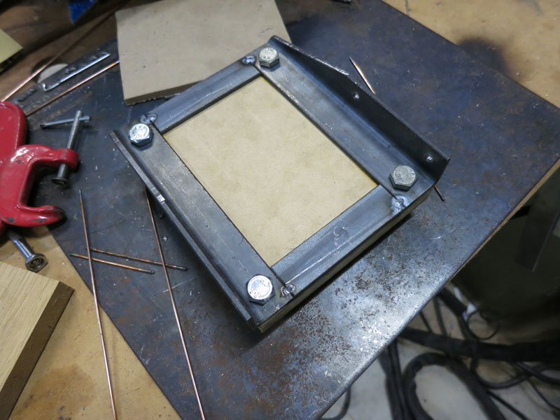
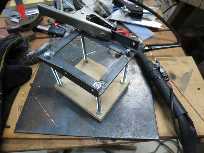
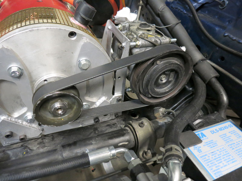
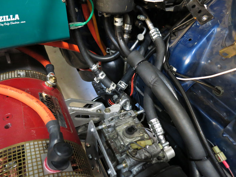
Air ConditioningIn summer we Australians are very grateful for having air conditioning in our cars. The RX7 had A/C before conversion and I want to retain it after conversion. There are three basic ways to achieve this in an EV, the easiest route (and the one I have chosen) is to run the factory A/C compressor via belt drive off the traction motor's auxiliary output shaft. Although certainly the cheapest and easiest option, being attached to the traction motor means that the compressor stops when the vehicle stops, so if you're sitting at traffic lights, the cabin won't get any colder. However since there's a fair bit of "thermal inertia" in the system (i.e the cabin won't get hot instantly when the A/C stops), and I don't spend too much time in heavy traffic, I believe it'll be an acceptable solution. For reference the other two options are to use an extra motor to run the A/C compressor on-demand, or to replace the existing compressor with an electric compressor. The extra motor option avoids the stopping problem above, but is a fair bit more difficult and expensive to set up, and takes up extra room in the engine bay (of which I don't have much to spare). It becomes more valuable if the auxiliary motor is given extra duties, such as also running the original power steering pump and/or a mechanical vacuum pump. The electric compressor option is elegant but the most expensive, both in equipment and installation. (A common brand used is Masterflux.) Anyway, taking the simple option of running the compressor off the traction motor, I fabricated a bracket to attach the compressor to the side of the motor frame. It it attached via four M6 bolts to a couple of tabs welded to the motor frame, such that the compressor can be unbolted and left in the car if I need to remove the motors. The bracket has four threaded rods which go through mounting holes in the compressor, which will allow belt tensioning to be adjusted by adjusting locknuts either side of the compressor on the threaded rods. Unfortunately the new position of the compressor is lower and further back, so the original pipes were the wrong lengths. As such I had to get an A/C technician out to de-gas and remove the original pipes so I could finish mounting the compressor, then later get them out again to make new hoses and re-gas the system - a somewhat expensive exercise which I would recommend avoiding if you can! The re-plumbing and gassing had to wait until the drive system was up and running so the compressor could be spun up to ensure the system was working. In the pictures below you can see the compressor installed with belt drive from the motor's auxiliary shaft. The belt type is a 6PK poly-V. The pulley came from CBC Bearings, and EV Works helped me modify it to fit the motor's aux shaft. The second picture shows the new hose(s). It's a bit of a mess because there's also power steering and water cooling hoses all in the same area! Getting the A/C compressor to actually turn on was a bit of a challenge, since originally the compressor's clutch was controlled by the ECU (which was removed along with the engine). In fact the solution I ended up with was to piggy-back a weak inverse-logic TTL signal from the A/C switch in the dash, to some custom electronics consisting of an inverting op-amp and a MOSFET, switching the original pull-down wire from the aircon relay. I also had to wire the refrigerant pressure switch in series with the aircon clutch, since it too was originally managed by the ECU. Once again this was not the simplest/fastest solution (just adding a new switch for the A/C relay would have been much easier!) but it's nice being able to retain use of the original A/C switch in the dash.
Water Cooling CircuitThe Zilla controllers require a water cooling circuit to draw heat away from the controller. This usually consists of a small pump and small radiator. Not much heat is produced so the system is very small compared with, say, an ICE's cooling system. As mentioned in the Heating section, I opted to combine the Zilla's cooling circuit with the heating for the cabin. Time will tell if this provides enough cooling capacity for the Zilla - I may need to have an extra radiator I can switch in with a solenoid if water temp gets too high.
Continue reading -> Licensing and Testing
Comments
|
|||||||||||||||||||||||||||||||||||||||||||||||||||||||||||||||||||||||||||||||||||||


Zero Emission Vehicles Australia © 2024 :: Terms and Conditions, Privacy Policy, Payments and Delivery, Warranty and Returns