 |
 | Development of a Lithium Battery Management System |  | Ian Hooper, March 2012 | |
Introduction
Lithium batteries have been a revolution in energy storage, and are found in almost every mobile phone and portable computer in the world. They have also been an enabling factor for electric vehicles, offering sufficient energy density to facilitate a driving range that covers the vast majority of road users' needs. However some care in the use of lithium batteries must be observed, as they can be permanently and irreparably damaged through either overcharging, over-discharging, or overheating.
Each lithium cell is only a few volts, so in most battery systems (especially electric vehicles), many cells are used in series for higher voltage. In such instances, for complete protection it is necessary to monitor the voltage of every cell individually to ensure they all stay within safe operating voltages. |
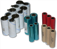
Some lithium cells |
The following table summarises the safe voltages of the most common chemistries:
| Chemistry |
Minimum Voltage |
Nominal Voltage |
Maximum Voltage |
| Lithium Cobalt (LiCo) |
2.5V |
3.6-3.7V |
4.2V |
| Lithium Manganese (LiMn) |
2V |
3.0V |
3.5V |
Lithium Iron Phosphate (LiFePO4)
* Most common in EV conversions |
2-2.5V |
3.2-3.3V |
3.65V recommended
(4.2V absolute maximum) |
In all cases, batteries tend to offer the best performance when operated warm (say 30-50°C), but may be prone to damage above about 60°C. As such another beneficial safety feature is to monitor cell temperatures to ensure they stay under this temperature.
The device which performs all this monitoring is known as a Battery Management System, or BMS. There are lots of BMSs on the market (click here for a great database of them) so there's little point developing your own – unless, like me, you enjoy the creative process. This article discusses the design of a BMS which I developed for use in my Mazda RX7 conversion. Schematics, PCB files and AVR code can be found at the end for those wishing to use the design, it is provided free but without any warranty, support or guarantees! (i.e use them however you like but don't sue me..)
Design Requirements
|
The intended battery pack to monitor is an 88S8P arrangement (88 cells in series by 8 in parallel) of Headway 38120S cells, i.e about 300V 80Ah. The Headway cells were chosen due to their respectable power density, being about twice that of Winston (ThunderSky) or CALB (Sky Energy) cells, without being too much more expensive. I decided to go for a modular battery design consisting of blocks of 8S8P cells, with a single BMS board monitoring each block (i.e 8 voltages monitored per BMS board). The RX7 would have 11 of these modules in series. For development, however, I built an 8S1P pack of K2 26650EVs - a nice small test pack to work with on the bench (pictured below). |
|
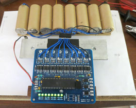
"Here's one I prepared earlier.."
Prototype BMS connected to K2 test pack |
The most important function of any lithium BMS is to monitor cell voltages, and be able to act if any go out of range. For my design, I decided to go with simple voltage dividers to reduce the 0-32V range down to about 0-5V, which a microcontroller reads with its onboard 10-bit ADC. With 10-bit resolution (1024 steps), the measured resolution would be about 32mV, which seemed sufficient (though a system which reports voltages could do with higher accuracy).
However an important aspect of any BMS which draws its power from the cells it's monitoring, is a low quiescent current draw, such that the BMS itself doesn't flatten the batteries if left for extended periods. Having voltage dividers permanently in-circuit seemed like a bad idea for quiescent power draw, so I added optotransistors which could switch each voltage divider on and off. These are each on for less than 1% of the time, which hugely reduces quiescent current. |
As a way of signalling other systems regarding any battery errors, I went with small solid state relays. These switch with a far lower input current requirement (a couple of mA) compared with physical relays, which helps minimise BMS power consumption. I used Vishay LH1546AD devices, which only cost a few dollars each. There are three output relays: one to signal over-voltage (stop charging), one to signal under-voltage (stop driving), and one if the shunts are on (optionally, throttle back the charger for a balance charge).
Another useful feature of BMSs is pack balancing, which can compensate for slight differences in self-discharge between cells. The easy way to do this is shunt balancers, which basically bleed off some power if a cell voltage goes above a certain threshold, to stop that cell going any higher while the other cells come up to charge. Many BMS designs utilise 5W resistors to dissipate the extra energy, but for my design I used TIP102 darlington transistors straight across the cells, switched by the microcontroller via optocouplers, with a weak base turn-on to restrict current flow. The result is a few amps of shunt current, which must be dissipated into a heatsink which the transistors get attached to. In this way, I can use a much bigger heatsink (even using the vehicle chassis) to get rid of shunt energy, rather than use resistors which get hot (potentially a fire hazard).
The final safety feature of the BMS is temperature monitoring. Lithium cells can be damaged if they get too hot, so thermal protection is quite valuable. I added dual temperature sensor inputs, with one thermistor attached to the shunt heatsink, and one attached to one of the cells. It's calibrated for about 60°C - so if either cell temperature or the shunt heatsink go above this, it can stop the charger and/or motor controller.
Another component of note is the Recom R785 power supply. These are a 5V switchmode power supply which is pin-compatible with typical LM7805 linear regulators, but much more efficient. In this application efficiency of the power supply is around 90% instead of 17% for linear. Although the Recom is an expensive part (about $10 each), I figured it was worth the cost to minimise the BMS's power consumption. From tests, the BMS appears to consume under 10mA, so would take several years to flatten a typical EV battery.
Electrical Schematic
After prototyping/verifying the various systems described above on breadboard, it was time to create the schematic and PCBs. For such tasks I use Eagle, from Cadsoft. It's one of the most popular and (I believe) best free PCB programs out there, and is supported by most PCB manufacturers (so you can send them Eagle files instead of Gerber). The picture below shows the schematic I came up with. To help clarify the circuit, click here for a labelled version.
Screenshot from Eagle PCB (click for enlargement)
|
Parts list: (might not be 100% complete)
- 1x ATmega16A microcontroller
- 3x LH1546 solid state relays
- 8x TIP102 darlington transistors
- 1x Recom R785.0-0.5 switchmode regulator
- 18x FOD852 Optocoupler
- 18x 10Kohm 1% resistors
- 12x 1Kohm 1% resistors
- 8x 4.7Kohm resistors
- 3x 2Kohm 1% resistors
- 1x 1.5Kohm resistor
- 1x 5.1V zener diode
- 4x 1mH choke
- 1x 50mA polyswitch
- 3x 1uF capacitors
- 8x 3mm LEDs
|
The first thing you might notice is a lot of optocouplers, two per cell in fact: one for voltage sampling, the other for enabling the shunt transistors. The top right section shows the eight transistor shunt units, and the bottom right shows the voltage samplers. The samplers are activated one at a time, so all use the same low-side resistor and feed to a single ADC input pin, which means in theory the design could be extended to a larger number of cells - though with 10-bit resolution the accuracy goes down with each cell added, so a better ADC chip may be needed.
Bottom left shows the solid state relay outputs, above that the ATmega16A microcontroller. This is a great micro with a lot of I/O pins, though the DIP40 (through hole) package is pretty huge and takes up a lot of PCB space. Top left is the power supply including capacitors and noise choke, and top middle is the temperature inputs - voltage divider plus some filtering before connecting to the AVR's ADC pins. A good rule of thumb when designing any microcontroller circuitry is to have noise filtering (chokes and/or RC filters) on every input, and buffers on every output. This prevents EMI noise from reaching the microcontroller pins and causing electrostatic damage to the microcontroller. There's a lot of info on the internet about designing good noise-immune circuitry, here's one of the better documents I've come across.
As an afterthought while doing the PCB design I also added an opto-isolated serial interface to the circuit, which in theory could be used for cell voltage reporting etc, but I haven't actually tested it or implemented anything in software.
PCB Design
Once the schematic design was complete, it was time to lay out the PCB. Doing PCBs can be quite an artform - easy enough to start with, difficult to do well, impossible to perfect. I actually find it quite theraputic.
The final PCB design is shown to the right. Click here for a version with labelled overlays summarising each section. The blue background represents a ground plane. This is one of the most important aspects of PCBs designed to operate in (EMI) noisy environments such as electric vehicles.
With a 2-layer board like this one, anyone familiar with PCB design will know how much more difficult it can be to lay out the rest of the circuit with only a single layer for all other tracks! I could have gone for a 4-layer board of course, but they're more expensive.
It's mostly through-hole components because I find them easier to work with for hand-assembled boards than surface mount. The downside is much bigger component footprints, and hence bigger and more expensive boards. An upside of larger footprints and pin spacings is that it's easier to route boards with fewer layers. |
|
The transistors are shown on the top but actually get mounted below the PCB, so that their metal tabs can be fastened to a heatsink (with insulator between, since their potentials vary).
Another "gotcha" with construction is that the actual resistor values in the voltage samplers is quite critical. They are rated to 1% tolerance/error, but over 32V range this becomes quite significant (~30mV). As such, when building the boards I manually matched sets of 8 resistors to within 0.1%.
In the past I've etched PCBs myself, but these days I don't think it's worth my time. PCB manufacturing companies can do it quite economically and with much better results, so I prefer to outsource. The two companies I have experience with are Gold Phoenix PCB and PCBCart. I've never received a single faulty board from either company. Gold Phoenix (qualitatively) seem to do slightly neater boards and may be better if targeting mass production, but PCBCart have an easier online quote/ordering system for small orders. I got 20 of these BMS boards done for about AU$9 each, including FedEx shipping and the one-off tooling fee.
Microcontroller Software
The software that runs on the ATmega16 microcontroller was written in C, using the AVR Studio development environment. Despite ending up a few hundred lines long, the functionality of the code is pretty simple. This summarises the main loop (iterating at about 10hz):
- Sample each cell, flagging any above or below voltage thresholds
- Enable/disable shunts for any cells above the shunting threshold (3.6V)
- Set status LEDs - on for in-voltage, off for error voltage, or flashing when shunt enabled.
- Read temperature sensor inputs
- Set output relays if any cell was below, above or shunting respectively, or over-temperature
The complete code listing may be downloaded below. For those who haven't worked with AVRs before, the AVR Studio software is free from Atmel (with registration). You'll also want to install the WinAVR GCC compiler so you can code in C instead of assembly! To transfer code to the microcontroller, I usually just use an inexpensive USB AVRISP type programmer. (I also have a JTAGICE programmer which does some nifty things like in-system debugging, but it's overkill for simple projects.)
Build Your Own
For anyone interested to build their own BMS, you are welcome to download the Eagle PCB files and the AVR project/code from this project. To reiterate, these files are provided freely but without any warranty, support, guarantees etc. YMMV!
Total parts cost worked out somewhere around $50 per board in low volumes ($6/cell), so it's definitely competitive vs commercial BMSs.. depending on how much you value your own time! They take perhaps an hour or so per board to construct.
I would stress that with a mission critical application like a BMS, you must be very confident that the system is working as it should before you deploy it in any real-world applications. Damaged batteries are not worth the risk! (That's why we run BMSs in the first place, right?)
~Ian Hooper, March 2012
Comments| | Scott Speight on 9th May 2012
ian, they ought to knight you just for the presentation of this material, not to mention the excellent content. Wishing you miles of smiles and looking forward to another visit with Steve when you can fit us in. | | |  | | | Ian Hooper on 10th May 2012
Thanks for the kind words, Scott! |
|
| | dev on 4th Jun 2012
Hi thanks for posting this article i would like to know how can we validate this result ? | | | | | | Ian Hooper on 7th Jun 2012
Hi dev, you're welcome to download the resources if you want to build your own, links just before this comment section. I mostly wrote this article just to give others some information and ideas for BMS design, I haven't really tested the system enough myself to be 100% confident with it long-term yet! (I'm still building the electric car it'll be going in.) So as they say: Your Mileage May Vary! |
|
| | EVSidekick on 31st Jan 2014
I like this design. I'd especially like to add bluetooth to the serial output via one of the low-cost serial->bluetooth boards (eg jy-mcu). That would allow an android-based dash display of all the status values. (potentially also charge status if the bluetooth has enough range).
Any chance that you could decrease the X-dimension of the board to < 10cm (it's currently 103.11mm). iTlead studio can do 10 10x10 board for ~$20. I can't edit your file in Eagle lite. |
| | Joshua Ngalande on 10th Mar 2014
Thanks Ian your Blog is amazing. Am spending a good amount of my intenet time reading all your articles. All great pieces. Thanks for all the information shared. |
| | Rusdy on 3rd Jun 2014
"Doing PCBs can be quite an artform ... I actually find it quite theraputic."
You have serious problem, but a good one, please do go on. There are lots of details in your findings (like the 78XX replacement, etc etc).
I learn a lot what BMS do (and do NOT) just reading your article here. 'Devil is in the details' they say, and you've addressed and document most of them. Kudos!
Can't wait your new project, seems like in recess? | | | | | | Ian Hooper on 4th Jun 2014
Thanks Rusdy. This BMS design eventually evolved into our BMS12 product, but went through so many changes as to make it almost completely different!
The latest project on the go here is converting a Honda NSR150 motorbike to electric - should be finished in the next month or so and info + pictures published on the website soon after. |
|
| | EVSidekick on 9th Jun 2014
This board has the input (12V) connected to HV8. That doesn't seem correct.
So far BlueTooth is looking good. |
| | EVSidekick on 30th Jun 2014
It seems to me that, because the power supply is non-isolated and the grounds are tied together there's no way to stack these boards to measure more than 8-cells. That would seem to be a fundamental design flaw that makes this design unusable. Sorry that I built a few of these, but glad I discovered it before actually hooked up cells. Maybe an isolated supply in front of the board? However, I'm starting wonder about the darlington circuit and using the cell/charger voltage as the gate. Since the purpose is to shunt/bypass I think that the way that's set up may be problematic. Untested theory, so I may be wrong. | | | | | | Ian Hooper on 30th Jun 2014
Hi, since the microcontroller's ADC is being used for cell voltage measurement (through resistor dividers), it does need to share its ground reference with the cells. But the solid state relays (LH1546) outputs are isolated from the rest of the board, so the signals can be safely daisy chained between multiple modules. |
|
| | EVSidekick on 30th Jun 2014
Sorry Ian, my misunderstanding of how you're powering the board, please ignore that last commented. |
| | SKYLOGGER on 25th Aug 2015
Hi Ian:
For your proto build, did you get PCBCART or Golden Phoenix to make your boards? Most PCB manufacturers keep the Eagle files in case of repeat jobs. If they run a repeat, they do not charge for tooling again. Is there a PCB part number/description or order reference I can give them
so they can look it up and see if I can place an order without having to pay tooling again (since that was already done by you). Just hate paying for work that has already been done by the PCB Manufacturer already.
| | | | | | Ian Hooper on 26th Aug 2015
Hi, I can't remember who did these PCBs for me, but lately I've been using Seeed Studio and PCBWay, who both have no tooling cost (and usually seem to work out a fair bit cheaper than PCBCart or Golden Phoenix - at least for small quantities). |
|
| | SKYLOGGER on 26th Aug 2015
Thank you for the quick reply, I've ordered some PCBs from PCBCart, they did not charge me tooling since you already paid that on your first batch. I plan to build some of these boards and try them out with some ex- I-MIEV cells. The chemistry of these cells have a bit higher voltage, so I'm going to attempt to learn to edit the C code you've provided. Looks pretty easy since you put the voltage parameters at the very top easy to edit. I have BORLAND C Compiler that I use at work to generate dBASE .EXE program files. I'm going to try using that so I don't confuse myself having two different compilers and all the associated project files on the same PC.
I see there are 4 include files used: IO.H INTERRUPT.H DELAY.H and WDT.H Can you point me to where these include files come from? Sorry for the dumb question. | | | | | | Ian Hooper on 26th Aug 2015
Hi again, those include files are part of the AVR GCC toolchain, which you'll probably need to integrate with Borland C somehow so it knows how to compile code for AVRs - though it may be easiest to just get a copy of Atmel Studio, which is a free download from Atmel and handles this stuff for you. |
|
| | SKYLOGGER on 11th Sep 2015
On the BOM you list a 5.1v zener. The schematic is showing several places for TVS Diodes. Were you using 5v zeners to act as transzorbs? I noticed several spots on PCB with diode symbols and one spot with a wider pitch silkscreen rectangle with a cathode mark at the end of the row of optos. Did you use same type diode for all of these? What diodes / transzorbs did you use on your original RX build? I've got most of the parts in now so will start populating a PCB soon. The PCBs just came back from PCBCART. They look really good. | | | | | | Ian Hooper on 11th Sep 2015
Hi, looking at the schematic, I think the 5.1V zeners were there for reverse and over-voltage protection on the temp sensor inputs. I don't think they're very important though and could certainly be omitted. |
|
|


