|
 | DIY Capacitive Discharge Battery Spot Welder |  | Ian Hooper, 6 January 2012 | |
Many batteries come in a cylindrical format with no inherent means of interconnection (such as screw terminals). Two common examples are the 18650 and 26650 sizes of lithium cell. The best way to connect such cells together permanently is to spot weld nickel strips between the terminals. (Soldering to battery terminals is not recommended due to the amount of heat that gets into the battery - potentially damaging the internal chemistry.)
A common method for doing this is with Capacitive Discharge (CD) spot welding, which basically involves dumping a pulse of energy stored in a capacitor through the nickel strip, causing localised melting of the nickel and welding it to the battery. (Critically, with battery spot welding the weld current must pass through two points on the same side of the battery terminal - not through the battery!)
Commercial CD welders typically cost several thousand dollars. But with a little ingenuity, you can build your own for a fraction of the cost. Here are a couple of examples of people who did it before me (and even more economically!)
Basically you just need a large bank of capacitors, a method of charging them up, and a method of discharging rapidly through heavy duty cabling and electrodes into the nickel strip. |
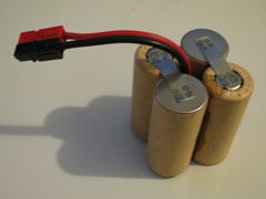
Example of a spot-welded battery pack

Close-up of spot welds
|
With a quantity of K2 26650EV cells sitting in my workshop, orphans from a cancelled project, it seemed like a good idea to build myself a CD welder such that I could assembly these cells into packs suitable for use in my various electric vehicle projects.
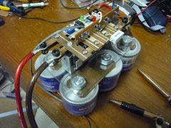
Completed CD spot welder |
My completed CD spot welder is pictured to the left. A box for it might be nice, but the naked electronics has it's own charm too. I won't go into explicit detail about the design because everyone is likely to do things a little differently, but will review my own component choices.
The heart of the welder is a bank of six Maxwell Ultracapacitors , each rated to a whopping 650 Farads, at 2.7V. Running six in series results in 108 Farads at up to ~16V. These capacitors feature very low internal resistance, so can deliver very high discharge current. Based on research, I learned that a typical battery spot weld requires approximately 200 Joules of energy. With this figure you can work out how much voltage and capacitance you will need for each weld, based on the formula for energy stored in a capacitor:
E = 1/2 CV² |
Hence at 15V, I would need about 1.8 Farad per weld. Clearly 108F is much more than necessary, and unlike the other designs above I need to be able to start and stop my pulse (not discharge the entire capacitor energy in a single weld), but having such a large capacitance does allow for many welds in quick succession, if desired. (I got these capacitors cheap off a friend. If I had to buy new, I'd probably opt for something smaller.)
Right is a labelled diagram showing the layout and control board on top (click to view larger).
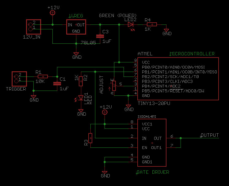
The pulse timer is based on an Atmel ATtiny13A microcontroller. The same function could also be done with something like a 555 timer, but I like the precision of a microcontroller, and it actually involves a lower total part count. This fires an IXYS IXDD4141PI gate driver, to switch a bank of MOSFETs.
I also installed a 100ohm bypass resistor to slowly discharge the capacitors. It's a bit of a waste of power while running, but avoids any surprises lest you come back a day later and the capacitors are still charged. |
|
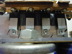 |
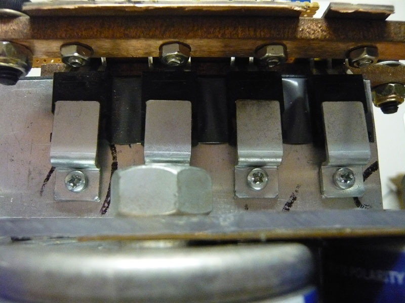
To switch the pulse current on and off, I'm using four IXYS IXFX120N20 MOSFETs, pictured left. They're actually part of an old motor controll assembly I had lying around. They are rated to 120A continuous or 480A peak current each, so blowing them up is fairly unlikely. I imagine it's overkill, but sometimes it's nice to have a bit of safety margin.
All the high power wiring is 8AWG, which has a resistance of around 2mohm per metre. Including electrode leads, I have about a metre worth in the welding circuit. The electrodes are made from solid copper rod with tapered ends. |
To charge the capacitors and power the logic circuit, I use a dual-output laboratory power supply. Separate power supplies for capacitors and logic circuit must be used because the ultracaps charge very slowly (about a minute to reach welding voltage), and the AVRs don't particularly like such a slow ramp up of supply voltage.
As can be seen from the pictures at the top, the welds are quite small but hold on tenaciously and should be good for about 10A per spot. A good way to verify weld penetration (on a test weld) is to try tearing off the nickel strip. It should leave part behind on the battery, and a hole in the nickel strip where the weld occurred.
|
|
Nickel strip can be purchased from Powerstream or Sunstone Engineering. For those outside the United States, shipping is pretty expensive (if available at all). I'd be interested to hear from anyone who knows of a good source of nickel strip in Australia. And feel free to contact me if you have any requirement for battery pack assembly!
~Ian Hooper, 6 January 2012
June 2012 Update: Schematics, Repairs, Upgrades and Musings
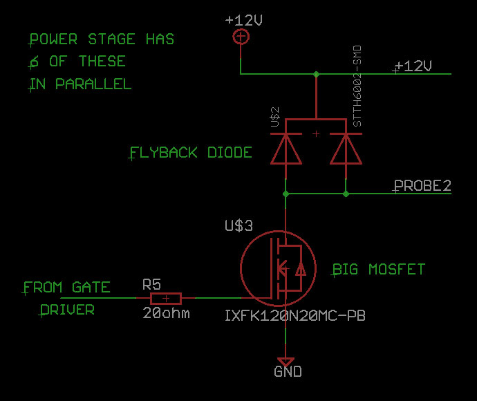
Schematics: Firstly, I've had a few requests for the schematics, so here they are (click for enlargements, or here for the Eagle file). On the left is the logic board, and on the right the power board (or, one of the MOSFET/diode pairs - need many in parallel). These are reverse engineered from the real thing so I hope I didn't forget anything! The power board layout is pretty much as per my most recent controller designs. Not something you can make on normal breadboard unfortunately due to the power involved! But mounting the MOSFETs on a heatsink and soldering thick wires directly to the legs is probably the easiest option.
|
|
|
I've also uploaded a copy of the microcontroller C code. It's pretty straight forward. Grab a copy here.
Repairs and Upgrades: The original power stage actually blew a MOSFET recently, after perhaps a few thousand welds. Fixing/upgrading it was quite a learning experienced, speckled with several other blown MOSFETs.
When one of the IXFX120N20s blew, I replaced the lot with IRFP2907s, a lower voltage FET with much lower on-resistance (about 5mohm instead of 20mohm). I also replaced the thin copper interconnectors between ultracapacitors with proper, clean busbars. It seemed like a good idea, but without realising the consequence at the time, I had greatly reduced the overall resistance of the weld circuit, which greatly increased weld current, and blew the new MOSFETs!
Turns out the cumulative resistance of the equipment is kind of relevant in getting the correct weld current. (In hindsight, I could have just welded at a much lower voltage to keep current lower.) Anyway, not having any more IRFP2907s on hand, I did another rebuild using IRFP4668 FETs, and upgraded to six instead of four devices in parallel, to give a bit more headroom. So far so good. I now weld at about 11V instead of 13V for the same result, since the lower resistance (compared with IXFX120N20) means less voltage is needed for the same current, and the heatsink stays a lot cooler.
As for weld times and energy, using a 10A power supply, it takes about 10 seconds to recharge to ~10V between each weld (after dropping about a volt). So, about 1000 joules of energy per weld. I have read that the spot weld itself needs about 200 joules - not sure if that's per spot or for a pair, but at any rate it's clear that the equipment is soaking up most of the energy rather than delivering it to the weld. |
|
Musings: I think if I built another spot welder, I'd go with 1 Farad of normal capacitors instead of ultracapacitors. The ultras are intimidatingly powerful. I worry what would happen if my timer circuit failed and the capacitors discharged completely! I imagine a shower of sparks, and/or things getting burned. Also the ultracapacitors don't really speed up welding because for the best welds you still have to wait for the power supply to top them up to optimum voltage each time - so it's P/S limited. May as well be using a capacitor bank with a single weld charge.
I did a bit of research on the options for a 1F high power capacitor bank, and for my money I'd go with 20x Panasonic 16V 47000uF. Digikey has them for about $5ea, so quite a bit cheaper than the ultracapacitor route. And, probably safer. As for the car stereo capacitors others have used.. I don't trust the cheaper ones to be either up to spec in capacitance or ESR. You need a lot of amps for good spot welds (ballpark a thousand, by my estimation), and their internal resistance may be too high (depending on brand, I'm sure - YMMV).
And a final note to anyone else out there building your own CD spot welder - take care! There are some pretty serious power levels involved which can make a mess if things aren't working right.
Comments| | Andrew on 20th Jun 2012
Can you please post a schematic of your control board assembly? Also, the part number for the gate drive should be IXDD414PI. Thanks for the great write up on your CD welder. | | |  | | | Ian Hooper on 23rd Jun 2012
Done! See update section above. |
|
| | Alan on 17th Jul 2012
I have 6 pieces of 47000uF 80V computer grade capacitors. Will these capacitors sufficient for welding battery tab?
As I do not have facility to compile the C code, could you please upload a copy of the 'HEX' code?
Thank you for the project. | | | | | | Ian Hooper on 17th Jul 2012
I'm not sure.. In parallel all six would only give you 0.28F which is a quarter of what most people use when welding at 12V. If you worked at say 50V the caps could hold enough energy to weld, but it'd be a much shorter pulse at much higher current (several thousand amps). And higher current is harder to control/switch, of course. |
|
| | Penny Imes on 29th Jul 2012
This is precisely the important information I'd been searching for. Incredible blog. Very inspirational! Your posts are so good and also detailed. The links you come with are also very beneficial as well. Many thanks :) |
| | Sylvia on 19th Aug 2012
Putting the ultra caps in series raises the problem that they might not be well matched in capacity. The nominal capacitance is only the initial mininimum, so the voltages across the capacitors will typically vary, leading to the possibility that one reaches its limit while others are still charging to bring the total voltage to the level intended.
| | | | | | Ian Hooper on 19th Aug 2012
Hi Sylvia, you are correct! (More info for the benefit of others: capacitor voltage is proportional to its charge divided by capacitance according to V = Q/C, and while series capacitors will necessarily all have the same charge in/out, variations in capacitance will cause variations in voltage as they charge up.) The easy solution is probably to monitor all the individual capacitor voltages while they're charging up and make sure none are exceeding their voltage limit. Generally you won't need any of them to approach max voltage. (The ones I'm using are 2.7V each so 16.2V theoretical max, but I only needed to charge them to 10-12V for welding; plenty of headroom for variations in voltage.) |
|
| | azzythehillbilly on 28th Dec 2012
Very nice blog. You have done agreat job. |
| | azzythehillbilly on 28th Dec 2012
I didn't understand the circuit well. ( too dumb) I tried discharging some capacitors through a dead short once. The inductance of the shorting bar caused the capacitors to be reverse charged almost to the smae voltage. With long leads and thus hugher inductance for sure. I don't understand how you prevented that from happening as I understand that the electrolytics are not too happy if reverse charged. Is there a diode across the caps to prevent that? | | | | | | Ian Hooper on 28th Dec 2012
Hi Azzy, hmm I'm surprised to hear you observed reverse voltages happening on the capacitor. I suppose it depends on the ratio of capacitance to inductance. A diode in reverse parallel with the capacitor would probably protect it, but shouldn't be necessary.. With CD spot welding, the capacitance should be far higher than the inductance (so the RLC circuit is "overdamped" and the caps don't go below zero). I guess my suggestion would be to try a larger capacitance, and maybe lower voltage? |
|
| | Mark on 2nd Jan 2013
If multiple ultra capacitors in series produce too much power that is difficult to control then maybe we can build a spot welder with only 1 ultra capacitor + step down charger ??? | | | | | | Ian Hooper on 2nd Jan 2013
Hi Mark, the snag would be the lower voltage, as most ultracaps are only rated to a few volts which probably couldn't push enough current through the circuit for a good weld. Typically the total circuit for CD spot welding may have say 10mΩ resistance (including capacitor internal resistance), which then needs 10V to achieve 1000A weld current (according to ohm's law, V=IR). 3V would only get 300A which may not be enough for a good weld. Just ballpark figures but you get the idea. Perhaps the same number of ultracaps but 1/6th the capacitance would be fine though, and should be cheaper than the ones I used. |
| | Mark on 3rd Jan 2013
thank you for fast response.
I found the specs for Maxwell BCAP3000 P270, and it seems that maximum peak current (1 second) is 2200A and 0.29 mΩ resistance. |
| | Mark on 3rd Jan 2013
I already have the Maxwell caps and I would like to build a very simple spot welder like Robert Thompson did, cos being honest I'm not sure if I could handle something more complicated. Do you think I have any chance to succeed? If yes what SRC do i need, 50A 100A, 200A? |
| | Ian Hooper on 3rd Jan 2013
That capacitor internal resistance should work well, but it's hard to keep the rest of the circuit low resistance, e.g 1 metre of 8 gauge wire for the probes has about 2mΩ resistance, and each connection adds a bit, etc.
As for SCRs, the problem is that you can't turn them off once they start conducting, the current has to stop flowing by itself, so would have no choice but to discharge the ultracap entirely - which is a lot of energy! Hence why I used MOSFETs, which can be turned off on command and do a timed pulse, whereas R.Thompson and P.Pemberton's designs have smaller capacitance which discharges fully so the SCR can turn off. Basically, unfortunately I can't see a way to use ultracaps with an SCR switch. Easiest option may be to build or buy a 1 Farad capacitor as per their designs! |
|
| | electric diagram on 5th Jan 2013
Can i have the electric diagram and the bill of the component of this spot welder? Thanks
can you send it to my email address xxxxxx@libero.it | | | | | | Ian Hooper on 5th Jan 2013
Hi, the electric diagram (including part codes) and AVR C code can be found in the "June 2012" update section. I don't have a bill of materials for the build because it was just a one-off. The hardest part to duplicate would probably be the power stage as you probably won't have suitable PCBs on hand, but can just solder large wires straight to the legs of the MOSFETs. |
|
| | John on 24th Mar 2013
Hi! I have eight BCAP1500 P270 Maxwell Ultracapacitors! How many capacitors should I use for battery pack welding? If parameters for each are 1500F and 2.7V. I thought 4 capacitors may work fine if delivered energy as follows is calculated: 2.7V*4=10.8V; 1500F/4=375F and in the end E = 1/2 CV² = 0.5*375F*10.8^2= 21 870J. Is total voltage and capatiance acceptable? What is your opinion? Ty already! | | | | | | Ian Hooper on 24th Mar 2013
Hi John, they would have plenty of energy and low enough resistance for the job, but you may need more than four for sufficient voltage.. I usually weld between about 10-12V, but it depends quite a bit on the resistance of the entire welding circuit (caps, probe wires, connections, MOSFETs, and the thing you're welding). Six might be a better number to work with so you can crank the voltage up a little if necessary. (As discussed with Sylvia in an earlier comment, because the capacitors vary by ~10% or so, you need to only charge to 10% lower than the theoretical maximum to ensure none get damaged.) |
|
| | Lionelb on 24th Mar 2013
Have you tried stud welding with say 2 or 3mm dia. studs ?
I'm looking for suitable studs and a stud-holder/gun. | | | | | | Ian Hooper on 24th Mar 2013
Hi Lionel, I haven't tried it with stud welding, no. As such I'm not really familiar with how much weld current or energy is required for that! But I suspect it'd be a fair bit more than we use for welding 0.01" nickel strips onto batteries.. |
|
| | bombastinator on 19th Apr 2013
I am interested in something even smaller:
I need only to weld very small wires together. 32-28awg. Specifically kanthal a to any old non-resistance wire of similar diameter.
I should be able to power the thing with nothing more than an AA battery I think. Do you have any suggestions on how to go about figuring out how to do it?
| | | | | | Ian Hooper on 19th Apr 2013
Not too sure about this one sorry! You might still need 10V to get the current flow but probably a much smaller charge/capacitance for a smaller weld. I'm not sure a AA battery would be able to put out the current required, but there's one way to find out! |
|
| | Portlablepowerman on 28th May 2013
Hi Ian, I am building off of your design and downloaded your c code, I went to verify/compile it using arduino 1.0.4 and IT TELLS ME: 'PB2' was not declared in this scope
FOR THIS: PORTB = (1<This is my first time doing anything like this.....Is this going to be a problem after writing to the attiny13? Thanks in advance for your help! -Greg | | | | | | Ian Hooper on 28th May 2013
Hi Greg, I was using AVR Studio with GCC compiler, which uses different libraries to Arduino. For me, PB2 gets defined when you include the header file "io.h". I'm not familiar with how the equivalent is done on Arduinos, but hopefully Google can tell you how to enable pull up pins on the Arduino! I think there are functions to do it or something. |
|
| | Portlablepowerman on 28th May 2013
Sweet! I will do the same then! Thanks! |
| | Phoebus Sparos on 30th May 2013
For what kind of weld spots do you use this?
I suspect small ones on jewellery, maybe up to things like cooking pots etc.
Would a larger version produce pulses of a few kA (5 - 15kA) of 200 to 300milliseconds each?
|
| | Pele on 1st Jun 2013
Ian, I'm attempting to build a similar CD welder. I notice that you didn't include pulse widths that gave optimum welds.
Also, I have a few thoughts to run by you.
Your welder has several MOSFETs in parallel, fed by a bus bar. This makes me wonder about the failures that you experienced.
Normally, one would consider the resistance of the bus bar to be negligible. However, when dealing with several hundred or possibly over a thousand amps such as in the case of a welder, microOhms count. Could the difference between the paths of the first and last transistor on that bus bar caused one transistor to handle more current than another?
Also, the MOSFETs were all triggered by the same gate driver. The datasheets for most MOSFETs list a maximum switching time and a typical switching time, usually on the order of Microseconds. Could this have caused one transistor to handle the welding current before any of the others switched on.
Granted the current and switching time differences might not seem like much, but could they have been contributing factors to the failure?
And if they did contribute to the failure of at least one MOSFET, would you know if you only had five of the working?
Four? Three?
I'm going to attempt to build my CD welder with an IGBT brick. Have you looked into these for either welding or for your vehicle motor controllers? | | | | | | Ian Hooper on 1st Jun 2013
Hi Pele, I didn't PWM the FETs because it seemed easier to just adjust the capacitor charge voltage to (proportionately) scale the pulse current. It also avoids (minimises) switching losses in the FETs, and (now) I also believe it avoids the need for any freewheel diodes.
My welders were basically built around recycled motor controller power stages - just what I had lying around, not necessarily the best tool for the job! That said the physical layout got tested thoroughly when I was developing it as a motor controller and I can confirm that the devices share the load well, even at much faster switching than the spot welder. I do think it was just a case of working the devices too hard, above their max current ratings. (Since I wasn't doing any current monitoring or limiting..)
I'm familiar with the IGBT bricks and know that most high voltage motor controllers use them, but don't use them much myself due to the lower efficiency compared with MOSFETs at typical EV conversion voltages, up to say 150V. So in a 12V spot welder IGBT losses may be pretty bad (probably over 10% of energy lost in the switch), but efficiency isn't such a big concern with a hobby spot welder, and I believe the IGBT bricks are pretty robust, so it should work.
(Actually if I did the project again I'd probably look at using 20V SMD MOSFETs, since running many in parallel should offer low enough on-resistance as to not even need heatsinking. This page gets a fair few visitors so it has been on my "To Do" list to design a better CD spot welder from all that I've learned since - perhaps something that could be offered as an inexpensive kit containing PCBs and busbars to make it easier for others to try building..)
Anyway good luck with your build! |
|
| | Pele on 1st Jun 2013
You have a control on your timing circuit that's labeled as Pulse Time Control and you also say that you didn't use an SCR like others do because you need both on and off control.
Perhaps I misspoke, when I said pulse width.
I didn't mean PWM, I meant how long is your weld current pulse?
Thanks again for your insight. | | | | | | Ian Hooper on 1st Jun 2013
The micro code translated that adjustment pot into a pulse duration range between 25-275ms or so. From memory I usually ran it somewhere in the middle of the range. It was a bit of an inexact science! It might be interesting to experiment longer pulses at lower current, or vice versa (though shorter pulse at higher current would need beefier switching devices). |
|
| | rektide on 17th Jun 2013
Audio caps are rated for 16V and 1F and if you get from a good batch as low as 250µΩ. Not bad for under $70, ho!
One author in the Endless Sphere e-bikes tab welding thread (Texaspyro) mentioned that he prefers always having two mosfets in series, such that if one of the pair shorts on (apparently a danger?) there's another in series that will still be able to turn off, and that that can often prevent what may well otherwise (and here i'm particularly fuzzy) have been the death of all the mosfets. I'm not sure how a shorted mosfet would jeopardize others, but on account of being a little timid about switching a kJ capacity reserve, spending twice as much on mosfets doesn't sound entirely like an unwise investment if there's some potential a heavily worked mosfet might lock into an on state.
Would love to see more shots showing how everything is mounted! Your RX-7 project has very clean designs, and your revamped controller here looks very nice too. Nice builds Ian. | | | | | | Ian Hooper on 17th Jun 2013
Yeah the two builds which inspired mine (Robert Thompson and Philip Pemberton, links at the top) both used audio caps. Probably the simplest option.
I'm not sure about the dual MOSFET thing. Failing as a short is a common failure mode, but I think if your circuit is working right and you're operating within the MOSFET specs, there should be no need to add redundancy. Of course, in hobby CD welders we're usually abusing the components a bit so I guess having stuff blow up is more common! Another reason I prefer the idea of only having a single pulse worth of energy in capacitors, instead of having to close the floodgates as well.. |
|
| | Portlablepowerman on 21st Jun 2013
Hello again Ian, I got everything together, and is looking good except the fet's I chose were IRL7833. I blew up several so far... I'm guessing it's because they are lower voltage than your IRFP4668....I'm not sure yet, so I looked up the IRFP4668 ones and can't seem to find but 2 at the most on anyone's shelf... do you know any suppliers in the states that carries them, or something as good? Also, got the code to program with arduino 1.4 via my arduino uno as isp. I also ended up drilling my buss bars for ic legs, then drilling and tapping perpendicular to it so I can "clamp" the fet and diode legs in place as you would on a terminal block. All in all, lot's of drilling, but I was able to pull blown fets in a minute, and isolate them within 3 minutes. I will get some material up sometime soon for others to see, in the mean time....know any suppliers for those elusive IRFP4668? :) Thanks in advance -Greg | | | | | | Ian Hooper on 21st Jun 2013
IRL7833 looks like a decent choice, their voltage rating should be fine unless you're getting some significant inductive v spikes. Note that TO220 packages aren't as beefy as TO247s (smaller package, smaller legs etc) so you'd probably need half again as many for the same power handling. Lately I've been getting IRFP4668s from RS Components - I think they are a global company? Good price too at about $6ea. But possibly better for CD welders would be ones like IRFP4468 or IRFP4368 for the higher current rating and lower on-resistance. Digikey has them in stock. |
|
| | Portlablepowerman on 22nd Jun 2013
Thanks a million! $6.52 each via RS Components (Allied Electronics) here in the states. The IRL7833s I have are the TO220s, worth seeing if they have them in TO247s then...they were dirt cheap, but I noticed one passed current without a gate signal...after removal of that one, others had the same issue after one or two welds...like the gate was stuck closed. I have a oscilloscope coming this weekend, and ordered 12 of the IRL4668s, so I will know more next round! -Greg |
| | issam on 23rd Jun 2013
Hello ian
I found the project very interesting microt spot welder, and thank you for sharing your information with everyone, I try to realize the same project I pocede capacity of 333 military farad 25 v, I put 4 mosfet IRF kind 3205 to control the discharge, I notice qund I load my capacity to burn the mosfet 25v, I c not for what reason,
At the beginning I try to charge the capacitor has SEVERAL value 12 v 15 v ac and give a result that is satisfesant, but I still do not understand why the mosfet is destroyed quickly noticed that the last mosfet connected to ground him that c will burn quickly, and thank you for all | | | | | | Ian Hooper on 23rd Jun 2013
Hi Issam, IRF3205 looks OK but as with Portablepowerman (above), you'll probably need to use more TO220s in parallel compared with TO247s, because they are a smaller package. The ESR of your capacitors and quality of wiring connections can make a big difference to the amount of current that will flow, so it can be hard to predict current at a given voltage, and it's possible that each of your IRF3205s are seeing hundreds of amps - which would explain why they are blowing. You could try say 8-10x 3205s in parallel, also start testing at a lower voltage - say as low as 5V, then increase in 1V increments until you get nice welds (hopefully without blowing FETs). |
|
| | meguit@rist on 10th Jul 2013
Great Project!
Can i drive the mosfet directly from micro controller instead of gate driver? couldn't get IXDD414 in my country, any replacement?
I don't have TO247 mosfet, only some IRL2003.
Thanks! | | | | | | Ian Hooper on 10th Jul 2013
Hi, most microcontrollers can only supply about 20mA from their output pins, which is enough to switch small / low power MOSFETs directly, but big MOSFETs have too large a gate charge and would end up turning on very slowly from only 20mA - which is quite inefficient and may damage the device when you're trying to turn on hundreds of amps. So in general if you're switching more than a few hundred watts, you're going to need to use a gate driver. I actually can't get IXDD414s anymore in my country (Australia) either! But for the last few years I have been using MIC4452s instead, which seem to be just as good. |
|
| | meguit@rist on 10th Jul 2013
will a IR2183 acceptable for the gate driver? | | | | | | Ian Hooper on 10th Jul 2013
It's not ideal because it's only got 1.4A output current (vs 12A for the MIC4452) so would have to switch the FETs about 8x slower, but it would probably work OK. Also it appears to be a half bridge driver, but you only need a single output for turning the discharge FETs on, so could just use the low side (bearing in mind that it is an inverting input on the low side). |
|
| | meguit@rist on 10th Jul 2013
hello Ian,
Thanks for yr prompt reply. I'll get MIC4452 as replacement. |
| | meguit@rist on 12th Jul 2013
Hello Ian,
Do I need to have the fly back diode on all paralleled mosfet or just 1?
Will try IRFP3206 soon. Just waiting for the MIC4452. |
| | meguit@rist on 12th Jul 2013
I'm thinking of disconnect the power source during spot. reconnect after 1-2 second. Will this reduce the spot current? | | | | | | Ian Hooper on 12th Jul 2013
Hmm I'm not sure regarding the flyback diode. I had them in my build because it was a recycled power stage from a motor controller, but there shouldn't be much inductance with the spot welder loop (and no PWM drive like a motor controller) so you might be able to get away without any flyback diode.. or maybe reduce it to a single diode with high peak current handling.
As for disconnecting the power source during welding, it should be fine. The power supply doesn't do much during the actual weld time. At most it'd only change weld current by the current rating of your power source, which is probably 10A or less, i.e maybe 1% of weld current. |
|
| | meguit@rist on 12th Jul 2013
Thanks for yr opinion Ian. I'll gather all the required components, etch the board & test out. Will post result once I done everything. |
| | howard in NZ on 20th Jul 2013
Hi, I have been looking at similar circuits for discharge magnetising.
Mostly higher voltage and current using computer electros.
Try Aliexpress.com (China)for mosfets.
Usually less than half price and freeshipping.
They may be counterfeit but none have been below spec so far.
Makes blowing them up fun not pricy.
One way to mosfet load share in rat's nest construction is to connect each device with equal length and resistance (inductance?) wire back to a common point.
Otherwise check out Ebay surplus hockey-puck SCR and stay easily within ratings.
Cheers, Howard. |
| | meguit@rist on 21st Jul 2013
hello Iran'
I have constructed my spot welder. everything's going well. except my China made 2.5F super cap was unable to output high current. It couldn't weld a simple 0.1mm stainless steel to mild steel. Weld time are adjustable from 1ms-255ms with pic micro controller. Any though? Could it be the cheap 2.5F super cap not as super as 2.5F?
I tried 4*27000uf+1*100000uf which is 208k in total & the results is better than the super cap. It weld 0.1mm very well but not 0.5mm. | | | | | | Ian Hooper on 21st Jul 2013
Yes, it is plausible that the Equivalent Series Resistance of the cheap 2.5F cap is too high for it to output the required current. Interesting that you got better results with just 0.2F capacitance! They must be better capacitors.
Most battery tab strips are about 0.1mm thick, that's pretty much all I've used my welder for. I expect you'd need a lot more power to weld 0.5mm material! |
|
| | meguit@rist on 21st Jul 2013
hello Iran,
thanks for yr prompt reply.
Can I use 3x5v 5farad cap in series on 12v supply?
this will get 1.66farad & up to 15v supply rite?
couldn't get a suitable super cap here. it cost me a lot. | | | | | | Ian Hooper on 21st Jul 2013
Hmm it should work.. the only caveat I can think of is that the ESR of three capacitors in series is 3x higher than one, so they would have to be very good caps to have a combined ESR low enough to weld with. (If I were doing another CD welder, I'd probably go with something like 20x 16V 47000uF in parallel, which I think are about $5 each from Digikey or similar..) |
|
| | meguit@rist on 30th Jul 2013
Hello Ian,
I just bought 27x27k.uf 35v cap today & tested 8 cap in parallel. This was able to weld 0.5mm stainless steel plate. Also, the welding voltage was at 24vDC.
After some search on Google I found that Tungsten tips was able to welds copper to copper. Do you know other material that do the same job?
Thanks! |
| | arran on 22nd Aug 2013
Hey thanks for the great tutorial and good to see you still check back here often. I was looking at Roberts design and wondering what you think of a 10v 10F capacitor bank to be charged with a 9v battery (more for novelty than practicality)? My two concerns are would the resistance of working materials be enough to prevent the caps from instantly discharging and also would 9v actually be enough to wield with? I'm reckoning that the low voltage and high capacity should be fine for doing a slow wield using only thyristor and manually removing the electrode from work piece to break the circuit. Though I could be completely wrong, any thoughts would be appreciated! | | | | | | Ian Hooper on 23rd Aug 2013
Hi Arran, not sure about the 9V battery idea.. there's a fair chance of damaging the battery if it's repeatedly seeing a virtual short circuit while charging up the capacitors! But may be an interesting experiment. If your contacts and wiring are all low resistance, 9V should be enough to do some spot welding - though it is hard to predict the overall resistance of your welding circuit, and this in turn determines how much current flow you get. 10F is certainly more energy than required for a single weld and things will happen pretty fast so it might be hard to weld consistently if you are using yourself as a timer! But it's probably not enough energy to do too much damage, so you could give it a go. Be sure to wear safety glasses! :) |
|
| | arran on 26th Aug 2013
I think the capacitor will charge quick enough that the virtual short will only be a couple of seconds, I would try not to discharge it completely so for multiple wields the cap will have a good initial resistance for subsequent charges (in theory...) I'll be using 200A thyristor and quarter inch copper as the electrodes, my main concern is that the 4x 2.7v caps will have their legs blown off/melted on discharging. Anyway I'll see how it goes, If i still have all my fingers I'll stick it on instructables. Cheers! |
| | Umut on 11th Jan 2014
Great work Ian, thanks for your effort. After I read, i also want to make one. |
| | Joel on 14th Jan 2014
Hello a very nice project , I starting a discharge spot welder from an old electronic book, can I submit you the electronic drawing?
Joel |
| | kyriakos on 16th Jan 2014
Dear Ian,
Please consult me the name and part numbers for a bank of IRFs to put in parallel handling 15 volts ,600 amperes outputed from a MIC4452 mosfet driver producing a 15ms pulse, because one IGBT is expensive.
Thanks in advance.
| | | | | | Ian Hooper on 16th Jan 2014
Hi kyriakos, yes those big single IGBT modules are expensive - and in fact relatively inefficient at low voltages (they'd generate about 1kW of heat at 600A). Using a few low voltage MOSFETs in parallel is much cheaper and more efficient. A good one to consider might be IRFB7430, at about $5ea. They claim to handle 195A continuous so you might get away with as few as three in parallel (though using more would be safer). |
|
| | Kyriakos on 16th Jan 2014
Dear Mr. Ian Hooper,
Thanks verry much for your yesterdays' quick response.
I am a 85 years old, DIYselfer begging for a complete technical advice like yours'. You are really unforgettable.
Thanks once again.
Kyriakos.
|
| | Richard on 12th Feb 2014
Hi Ian, I am considering building a tab welder similar to the other designs you mentioned, using a 1F, or so, capacitor. They use an SCR switch and you use MOSFETs. I am not very knowledgable in this area, but wonder if a switch is needed at all. Could I not just charge the capacitor, and then, while holding one electrode pressed tightly to the tab on top of the battery, touch the other electrode to the tab to release the capacitor's charge? | | | | | | Ian Hooper on 12th Feb 2014
It's an interesting idea. The first possible problem that comes to mind is that you kind of need the probes to be applying pressure to the contact before the discharge starts. If the capacitors were to discharge as soon as they touched the nickel strip, it might just melt a hole in the strip without welding it to the battery. As far as SCR vs MOSFET, either can work. SCRs can't be turned off (they turn themselves off once there's zero voltage across the power terminals), but with a 1F capacitor you just discharge it completely through the weld so there's no issue using SCRs if it works out more economical. |
|
| | kyriakos on 23rd Feb 2014
Dear Ian
I wired the + Terminal of the capacitors bank through 3 IRFB7430 Mosfets in parallel connecting their (source) pins to the positive electrode of the welder.
And the - Terminal of the capacitors bank conneting their (drain) pinds to the negative electrode of the welder.
A fly back diode is directing (showing) from Drain pin towards the Source pin.
Their gate pins only receive the pulse.
Am I correct ???
Thanks in advance.
Kyriakos
| | | | | | Ian Hooper on 24th Feb 2014
Hi Kyriakos, it sounds like you may have the MOSFETs wired up incorrectly. N-channel FETs are usually used as "pull-downs", so you'd need the capacitor bank +ve going to one electrode, the other electrode going to the Drain on the FETs, and the Source connected to capacitor -ve. The FETs will turn on when their Gates have more than about +5V relative to the Source pin (or capacitor -ve).. |
|
| | Kevin on 28th Feb 2014
Hello Ian,
Would you recommend high side switching over low side? I read that N channel MOSFETs work better on low side switching, and that for high side switching the gate voltage needs to be 5-10V above the load voltage.
My capacitors can take up to 20V, but the IRFP2907 FETs I have allow an absolute maximum gate voltage of 20V.
Just wondering if I'd lose much, if anything by going with low side switching.
Thanks! | | | | | | Ian Hooper on 28th Feb 2014
Hi Kevin, low side switching is easier and more common because N-channel FETs tend to offer more performance, plus your gate is a positive voltage referenced to the B- / ground. P-channel devices usually have higher on-resistance. You can use N-channels to switch the high side but need to do isolated gate drive (since the gate is referenced to a floating potential) which is a bit of a pain. |
|
| | Kevin on 1st Mar 2014
Low side it is then! Have you found a better source of nickel strip yet? I too live in Australia (Perth) and all I can find are small rolls on eBay that comes at 0.15mm thickness which is a bit much.
I've seen Sunstone engineering, but their postage cost is quite excessive in my opinion. | | | | | | Ian Hooper on 4th Mar 2014
Yeah I got my last bits from Sunstone.. and I can only agree that postage to Aus is very expensive :( |
|
| | kyriakos on 4th May 2014
Dear Ian
I finished my welder but the weldings are not strong.
I seems that the currents obtained is not hot enough
The signs on the strips (sunston) are hardly seen.
Comporents , wiring and adjustments used:
6 Maxwel Ultra Capacitors 350 farad 2.7 volts in psrallel.
15 Volts Initial Charging before each test.
45 Minutes initial Charging time.
10 ms single pulse adjusted with oscilloscope.
Charging controler with a 555 and a Mic 4452driver.
Output discharging circuit :
3 (three) IRFB 7430 in parallel with their pins
soldered on a thick wire.
Data scheet of IRFB 7430 (silicon limited 409A
package limited 195A
I raised the charge voltage to 16 volts but without improvement.
I suspect that the t h r e e IRFBs are not sufficient
to give a hotter pulse.
I will appreciate if you give me your advice once again.
I am ready to repeat doing the entire welder from the very
beginning.
Thanks very much
Kyriakos
|
| | kyriacos on 4th May 2014
Correction:
The 6 Maxwel capacitor are connected in series not in parallel. Sorry
Kyriakos | | | | | | Ian Hooper on 5th May 2014
I would recommend bumping up the pulse time, maybe go up in 10ms increments until you get good results. From memory I was using much longer pulse times than 10ms with my original prototype. Spot welding is basically about quickly putting a large amount of energy into a small area to melt things together. Energy is of course power (or volts x amps) x time, so bumping up the time can compensate for lower power delivery.
If the current is too low it’s probably the accumulation of resistance throughout the whole circuit. The IRFP7430s shouldn’t be the bottleneck. They have 1mohm on-resistance so three in parallel should only have 0.33mohm on-resistance - which could in theory allow thousands of amps to flow at 12V! Of course their little cases would probably explode if a thousand amps flowed through them, so you may end up needing to run more in parallel for sufficient current capability.
Be careful charging those caps up to 16V as some may end up with a higher voltage than others (due to manufacturing tolerances in the capacitance), and may exceed their 2.7V rating. Perhaps each check with a multimeter to make sure. You should be able to get good results around the 12V mark with longer pulse times. |
|
| | kyriakos on 5th May 2014
Dear Ian
Thank you very much for your prompt and really c o m p l
e t e from any aspect response.
It gave me more satisfaction by readint it than dismantling
the entire Project. I have now the solution in my mind ready to play with the smal trimer adjuster in my 555 timer output.
Many thanks for shearing your knowlodge and experience.
Kyriakos.
|
| | Sergioty on 6th Jul 2014
kyriacos, looking at your design, it looks like your are not getting enough current due the internal resistance of the supercapacitor. They have around 0.030 Ohm of internal resistance and at 2.7V the maximum current they can output will be I=2.7V/0.030Ohms around 90 Amps that is low for a Spot welder. If you place the capacitors in parallel, for example two, the maximum current will be around 180A, but the voltage will be low (2.7V). Probably you will have better results with 20 electrolytic capacitors of 82000uF x 16V in parallel. That will give you around 1,6uF at 16V. Each electrolytic capacitor has around 0.008 Ohm of internal resistance, so the theoretical maximum current will be I = 16V/0.008Ohm = 2000A during the discharge. Having all them in parallel you could have 20x2000 => 40,000A, but of course the overall resistance will limit the current an the capacitors are not able to support all this current. Some commercial spod machine have 2F or 4F and have two pulses of around 3.5ms. First clean the second weld.
The SCR will drop a lot the voltage that means you will need higher voltage capacitor which is expensive. It is better use MOSFETs which have very low internal resistance when on so you can have most of the energy stored in the capacitors.
I hope I could help. I am thinking also to design a machine for my own use and I was looking around what is available.
|
| | kyriakos on 19th Feb 2015
To Ian Hooper and to Sergioty
Many thanks to your respective responses.
My completed Ultra Capacitor discharge spot welder still
gives disapointing poor results, low or no penetration.
Below I remind you some specifications:
6 Maxwell Ultra Capacitors 350 Farad 2.7 volts put In series, charged to 15 volts DC.
Pulse controller on bread Board with a 555 and a MIC4452 driver. Adjustable pulse time with potensiometer 25-250 ms.
8 IRFB7430 in parallel mount on their respective heat sinks
The whole thing wired on thick wires especially the out put starting from the negative (-) terminal of the capacitor bank to a common (unique) ground - negave bar, then to the sources of the 8 mosfets, then the 8 exiting drains in parallel from mosfets to the negative black prod.
Then from the other side, starting from the charger to the positive (+), terminal of the cacitor bank to the + positive Red prod. Every thing on a 4mm.cable, in order to avoid, resistance of the project.
I will wait your precious response.
Thanks in advance. | | | | | | Ian Hooper on 20th Feb 2015
Hi kyriakos, it sounds like you have a good set of components so the main possible problem that comes to mind is the total circuit resistance may be restricting current flow - in particular, connections between the capacitors since there's basically a dozen joints there. I noticed a huge difference when I cleaned the oxide layer off the copper interconnectors in my build and added contact grease (Noalox), which showed me how critical good connections are with this design! We'll see if anyone else has any ideas/comments too.. |
|
| | kyriakos on 20th Feb 2015
Dear Ian
Thanks once again for your almost immediate response.
You are unforgettable. I keep testing particularly the output of my project till I find why this lack of 100 amps. current during the crucial discharge (pulse).
I see a noisless small spark comming from the six maxwells.
I must say, that when I charged a s i n g l e Maxwell Ultra capacitor 350 farad to 2.5 Volts which I have as spare and tried to short circuit his terminals with a wire I saw the wire to vaporise.
Please excuse me for my weakness in English.
Kyriakos
|
| | Kirk on 25th Mar 2015
Would these be able to arc weld metal, using traditional welding rod? |
|