|
 | Mazda RX7 Conversion |  | Ian Hooper, 2012 | |
 |
Specifications in brief
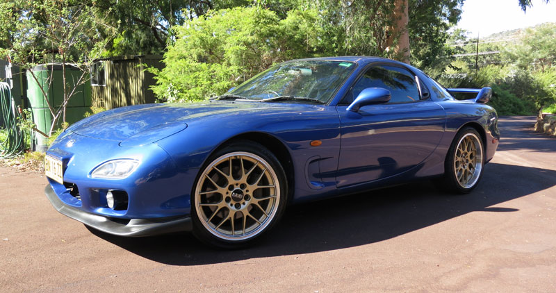
- Donor vehicle: 2000 Mazda RX7 RS
- Power: ~300hp
- Torque: 700Nm from 0rpm
- Range per charge: 120km
- Performance: 0-100 in approx 5s
- Weight: 1440kg (+12% on OEM)
- Balance: 51.5:48.5
Components
|
Getting Started
Introduction
Welcome to the construction journal for my Mazda RX7 electric conversion. There's quite a lot of content so you can skip to chapters of interest using the links above, and feel free to leave a message in the comments sections if you have any questions!
It had been a long-time dream of mine to build an electric car with performance enough to compete head-to-head on a race track with petrol vehicles. I believe such an EV can make great strides in dispelling common misconceptions about EV performance, and actually make people want an electric car. I was inspired by US EV racing pioneers like John Wayland (White Zombie) and the Pro EV team (Electric Imp) and wanted to bring some of that excitement to Australia.
Back in 2007 I started my first EV conversion, based on a 1990 Mazda MX5. The conversion went pretty well and it was a nice car to drive, but due to inexperience and budget constraints, its performance wasn't really worthy of competition use. So in 2011 I decided to sell the MX5 in order to help fund a new EV conversion. With greater budget in mind, there was only one choice of donor vehicle for me: a Series 8 Mazda RX7 Type RS, one of my all-time favourite cars and arguably one of the finest sports cars ever made. |
|
After a few months of unsuccessful searching for the perfect donor vehicle here in Australia (they're not very common, and many have been abused or have accident history), I instead ended up importing directly from Japan. In the end it took about six months from the sale of the MX5 to having an RX7 sitting in my workshop! But by late March 2012, the electric conversion officially began.
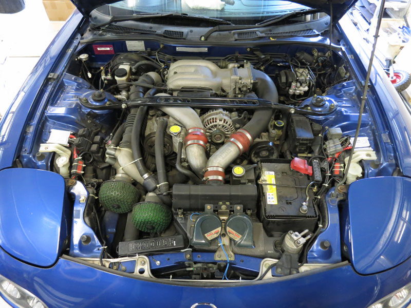
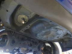
Engine Removal
For the MX5 conversion I got a couple of friends to help me with the arduous task of engine removal. It was a pretty awful job, and I could feel myself procrastinating about having to do it again with the RX7. So this time I took the easy option, and enlisted local RX7 specialist Rotomotion to do the job for me. Having a workshop remove the engine for you is not cheap, but it is a big job so saved me a lot of time, plus they're helping me find a buyer for the old engine.
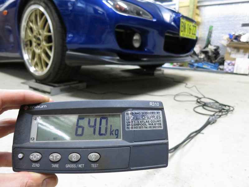
Rotomotion also removed the gearbox, radiator, fuel tank, fuel pump and exhaust. I weighed the car before and after removal using load cells borrowed from EV Works. This is invaluable data for knowing how much weight allowance you have to play with, and where it should be in the car in order to maintain good weight balance. Apart from for performance reasons, the Department of Transport prefer to see vehicles with a converted weight and balance as close as possible to the original, so they know that the driving characteristics will not be compromised.
It came out at a total of 385kg removed, with 252kg front and 133kg rear.
Initial component choices
Controllers: Seduced by the idea of higher efficiencies and regenerative braking, I had hoped it might be feasible to use an AC drive system for this conversion. But after looking long and hard at the available options, I was unable to find anything which could remotely compete with a high-end DC system in terms bang-for-buck. (My budget is not unlimited!)
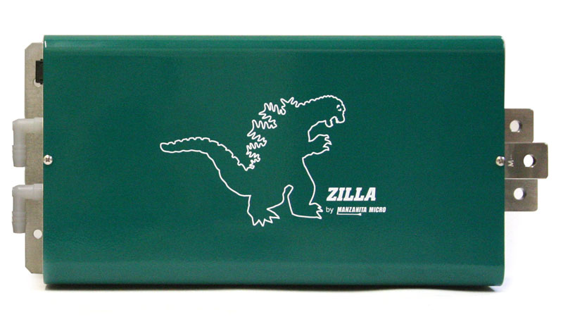
The best candidates I could find were the Tritium WaveSculptor 200, and either a rewound industrial AC induction motor, or something more exotic like an Ultramotive motor. The Tritium looks like a great controller, and (for AC) not bad value at AU$6600 for 165kVA peak power ($40/kVA). But compared with a CafeElectric Zilla2K EHV with 680kVA for about AU$5500 (AU$8/kVA), there's still a massive price difference between AC and DC controllers - all the more pronounced in very high performance vehicles (I would need four WaveSculptor 200s to equal one Zilla 2K EHV). So, with a touch of regret, I rationalised that DC was still the way to go.
At the time I was deciding, the most powerful controller on the market was the CafeElectric Zilla 2K EHV. These have been around for many years and have been used in most high performance EV conversions around the world, so seemed the logical choice. (EVnetics, who make great controllers, recently announced their ridiculously powerful Shiva controller, offering 1200kVA peak! But I won't be going that extreme; as well as being almost twice the price of a Z2K, I don't think I could fit in either motors or batteries big enough to justify a Shiva.) |
|
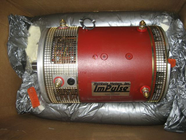
Motors: For safety and traditional reasons, most DC motors for road-going car conversions are designed to work around the 120-150V mark. So if using the full voltage capabilities of the high voltage Zilla2K, the best way to go is dual motors. When driven by a large controller, there is so much torque that a gearbox becomes unnecessary, and the motors can be coupled directly to the tailshaft - known as direct drive. (In fact a single 9" or larger DC motor with a 1000A+ controller is sufficient for direct drive.) Dual motors also opens up the possibility of series/parallel switching, which gives the electrical equivalent of two gears - though I don't expect to need this. Brand wise, I believe NetGain make the best DC motors for high performance applications, using very large windings and brushes to allow high peak current handling.
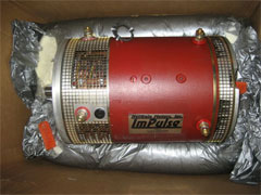
Netgain Impulse 9 motor |
Based on the specs and NetGain's performance graphs, I identified either the Warp 9s or the Impulse 9s as the best candidates. The Warp 9 has approximately 30% more torque per amp than the Impulse 9, but consequently about 30% higher back-EMF. In practice this means the Warp 9 would offer better low-speed acceleration, but the Impulse 9 would offer more consistent acceleration to higher speeds.
Some back-of-envelope calculations suggested dual Warp 9s would yield approximately 1.1Gs acceleration, and the Impulse 9s around 0.85Gs acceleration. Being skeptical that street tires would be able to hold on at over 1G acceleration, the Impulse 9 therefore seemed the better choice, and would offer more consistent performance over the whole rev range. Using the slightly smaller Impulses would also save around 25kg. |
Batteries: In all previous conversions I've done personally or been involved with, either ThunderSky (now Winston) or CALB batteries have been used. For many years these two brands have been the best value lithium solution for EV conversions, and in my opinion are still the way to go for normal road-going commuter EVs. However with only a ~5C real-world peak discharge rate, their power is a little low for race cars. So for this conversion, I had to find something better.
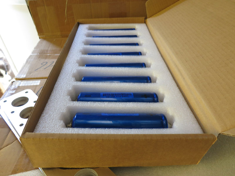
Manufacturer Headway have been around for a while, and their medium-sized (10-16Ah) cylindrical cells have been demonstrated in several EVs around the world with good results. So I arranged for some sample cells to test, and confirmed that their internal resistance of ~10mohm in a 10Ah cell is about (proportionately) half that of ThunderSky cells - suggesting approximately twice the power density. In a typical EV-sized pack, that yields a peak power of around 200kW, which should be plenty for a high performance EV (especially considering the superior torque and power band characteristics of electric drives). |

Some of the Headway cells for the RX7 |
Other components: Once the main items above had been selected, including settling on a nominal battery voltage of ~280V (88 LiFePO4 cells in series), the rest of the parts were easy enough to decide on:
- DC/DC converter: IOTA DLS-55 HV (200-320VDC version, well proven and economical)
- Charger: Zivan NG3 288V (not the cheapest brand but reliable / well proven)
- Power steering pump: Mocen 12V 500W (16 July 2012: actually I'm looking into a different option)
- Instrumentation: One of my ZEVA Fuel Gauge Driver Plus devices for battery SoC and current monitoring
- Vacuum pump: MES 70/6E (nice compact unit with inbuilt vac switch, Swiss-made automotive grade construction)
- Contactors: 2x Kilovac EV-200 (one per battery box - economical hermetically sealed contactors)
- Main fuse: Bussmann 500V 600A
The BMS was not so easy.. Being unfamiliar with any Battery Management Systems (BMSs) designed for Headway cells, and partly for interest's sake, I decided to design and build my own BMS for the car. More information about the BMS design can be found here. I'll also be using one of my EVMS units as the master unit.
With a little over 200kg of batteries, 120kg of motors, and perhaps 50kg of other equipment on board, I am estimating (hoping) the converted weight will be extremely close to the original factory weight.
Almost all of the components are coming from local Australian supplier EV Works (who I used to work for). The traction circuit will be quite similar to the "More Complete Wiring Diagram" I drew up a few years ago.
Design Stage: Motors
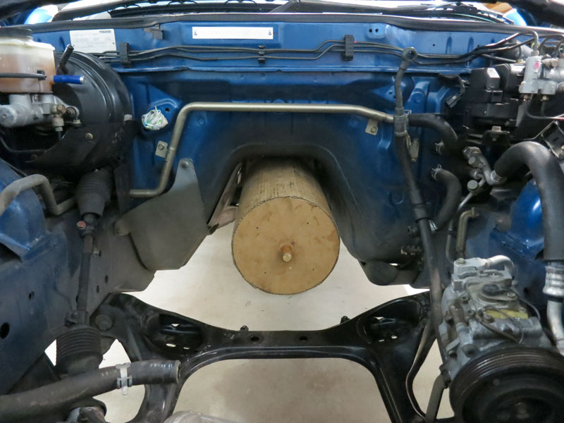
With the all the engine-related components removed and initial component decisions made, it was time to start designing how it would all fit into the car. The engine bay now had a vacant space around 700mm wide, 900mm long, and perhaps 500mm of total height - with many things to squeeze in!
The first components to fit are the motors, since there's little choice about where they can go (must connect to the tailshaft). The best place for them is as far into the transmission tunnel as possible, to leave maximum space in the engine bay for batteries etc. In the MX5 I had a fair bit of trouble getting the correct alignment from the motor to driveshaft to differential. If this is slightly off, it can introduce vibrations into the drivetrain.

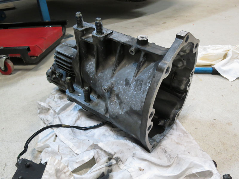
Final section of the gearbox (upside down)
|
As such although I will be running direct drive (no gearbox), this time I'll be reusing just the final section of the gearbox, which has the existing driveshaft and torque tube attachments, to ensure correct alignments. (The torque tube is a C-channel frame which rigidly connects the gearbox to the differential.) It also has the speedometer drive sensor in this section which will save me having to re-engineer a speedo sensor mount.
As a general rule, the more of the existing car you can reuse, the easier the conversion will be! So the motors would be mounted in-line, resting on the original engine mounts, and with the rear motor face mounted to this gearbox section. |
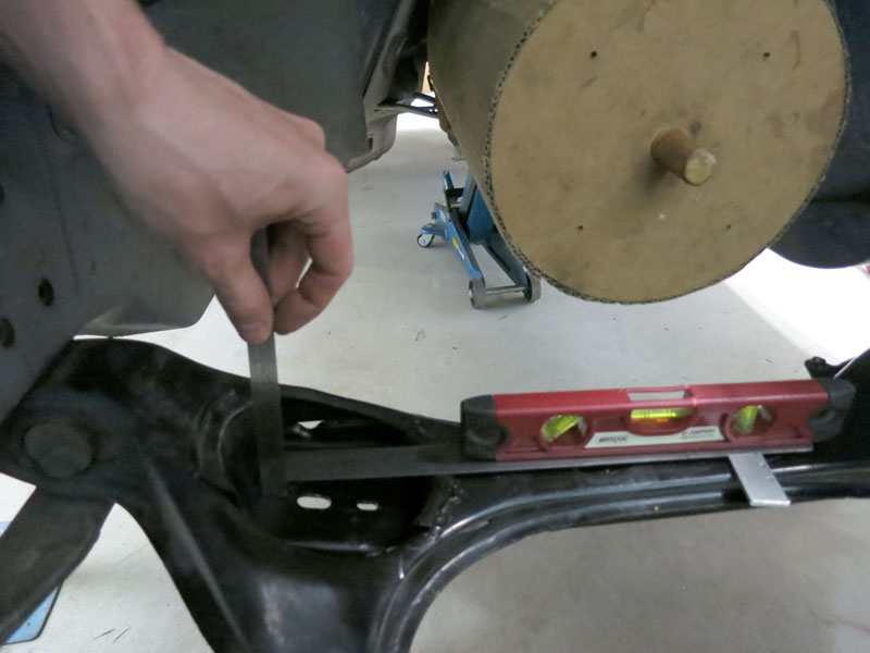
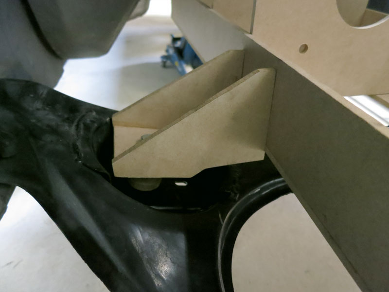
To verify fit in the tunnel, I mocked-up an adaptor place which would attach the gearbox section to a steel frame holding the two electric motors, which would rest on the old engine mounts. (I do a lot of prototyping with Medium Density Fibreboard / MDF, because it's easy to work with and I believe it's invaluable to actually build and test-fit 1:1 models before spending money on steel/aluminium! Prototyping with wood first often identifies issues or improvements early.)
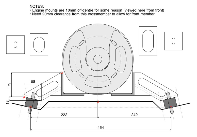
Once I was sure the motors would fit where I wanted them to go, it was time to design the frame which held the motors in place. What I came up with basically uses two 75x75x6mm equal-angle steel "rails" running the length of the motors, and four perpendicular 6mm plates holding both faces of both motors in-line. Then there would be legs protruding sideways out to the original engine mounts, through large rubber vibration mounts.
This steel frame alone will have an approximate weight of 15kg, which is not insignificant, but it does need to be pretty tough so I don't want to skimp.
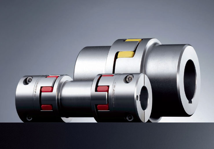
To join the motors mechanically, after consulting with local transmission experts Transeals, I've ordered a Rotex RR38 spider coupler. Ideally the motor shafts will be accurately aligned, but the spider coupler allows for slight misalignment if the framework flexes under load. |
|
Design Stage: Batteries
For a comfortable 100km+ range in a normal car (my minimum range requirement), you need around a 20kWh battery pack (200wh/km). With a ~280V pack, this meant a 70Ah capacity. As such a reasonable pack configuration would be 88S7P. The Headway 38120 cells are 330g each, giving a total battery weight of just over 200kg.
Empty rear end where fuel tank and
muffler used to be |
The obvious places for batteries to be installed in the RX7 was to have some occupying much of the remaining space in the engine bay, and some where the fuel tank was (just behind the rear wheels, beneath the boot area).
There is a pretty large potential space in the rear for a battery pack - around 800W x 600L x 300H mm. As it turns out, weight is more the limiting factor. The rear pack sits behind rear wheels, so actually contributes more than its own weight to the rear wheel loading. Also the motors are a little behind the front wheels, so would also be contributing a little to rear wheel loading too. As such, if I wanted to maintain comparable rear axle loading (Δ133kg), it would be necessary to restrict rear pack weight to under 100kg (approximately). As such I decided - as an initial target - to have a 40S7P pack in the rear, in series with a 48S7P pack up front. |
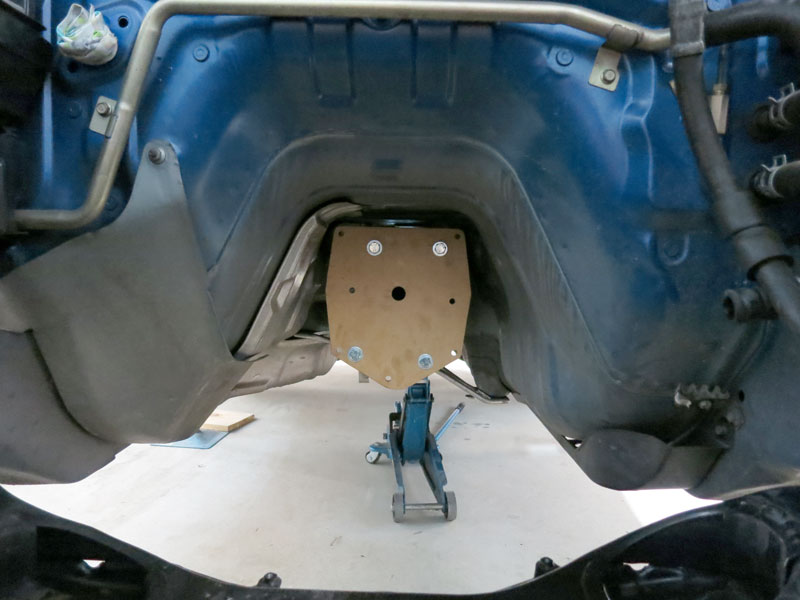
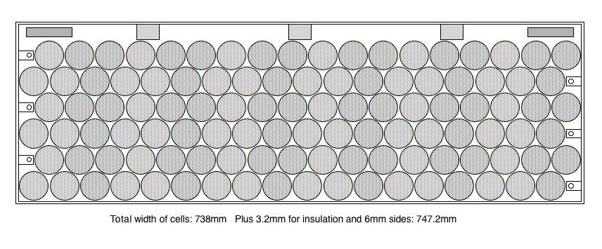
Due to the space occupied by the motors and other ancillary equipment planned for the engine bay such as the aircon compressor and power steering pump, there proved to be very little height left in the engine bay for the front battery box - about 250mm, which is less than the height of a stack of 7 cells. So after much headscratching and considering different battery configurations, I came up with an interesting way to fit 48S9P in the front. The image right shows the side view of a 12S9P arrangement, and there will be four of these across the width of the engine bay giving 48S9P. |
|
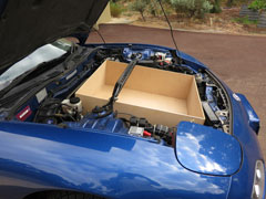
Mock-up of front battery box in engine bay |
The resulting 740L x 610W x 240H mm battery box would fit above the motor frame, sloping down slightly towards the front of the engine bay to follow the bonnet contour, leaving just enough space behind it to mount the Zilla controller. I haven't purchased enough cells for running a 90Ah pack so intend to just start with 70Ah, but will design the boxes for 90Ah because it's nice to have the option of upgrading to 90Ah in future (once I can afford some more batteries!). The image left shows the test-fitting of a prototype box of correct dimensions in the engine bay, including the motor frame underneath it.
The exciting thing about potentially fitting in a 88S9P pack is having over 25kWh in a small aerodynamic car like this may yield 150km+ range, as well as having ~30% more peak power than my initial expectations. |
For the rear battery box, as I mentioned before, there is an excess of space in the rear to fit the required 40S9P pack. For consistency the cell layout is a similar hex packing to the front box, but only 8 rows wide, and 5 rows deep. This gives a battery box size of 760W x 500L x 240H mm.
I'll be cutting out the floor of the boot including the spare wheel well and mounting the battery box flush with boot, with a polycarbonate cover for display purposes. |
|
Structurally, the battery boxes will be made from 3mm aluminium panels TIG welded into boxes, and lined with 1.6mm polycarbonate (which is both electrically insulating and flame retardant). There will also be 1.6mm polycarbonate panels separating each of the battery arrays.
Continue reading --> Drivetrain
CommentsThere are no comments for this page yet.
|