
Introduction
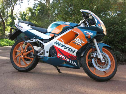
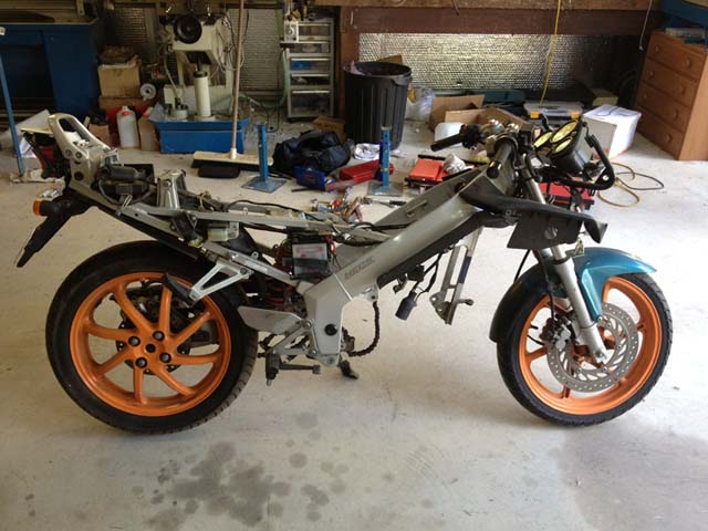
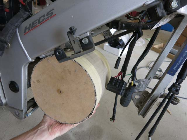
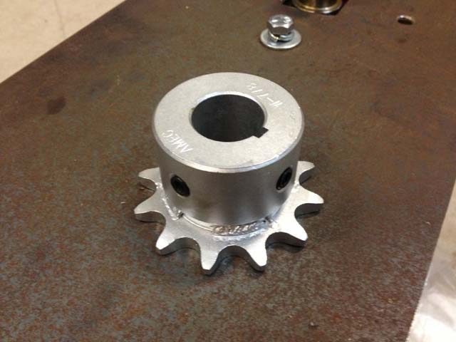
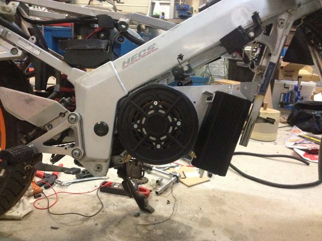
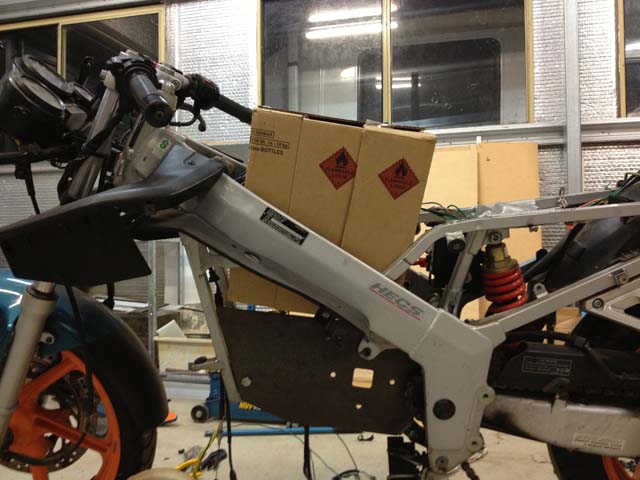
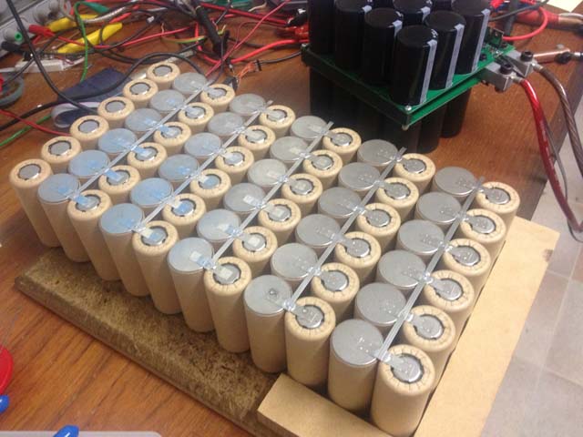
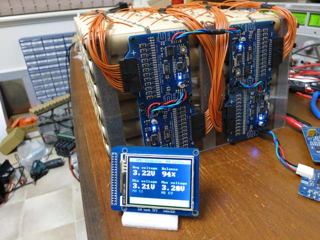
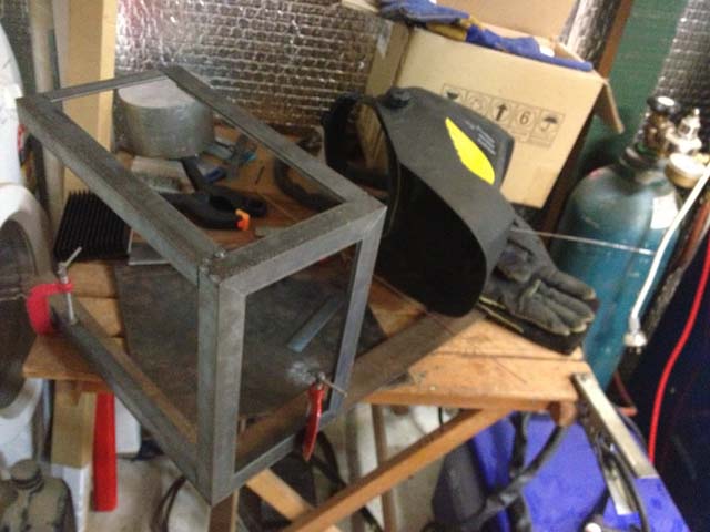
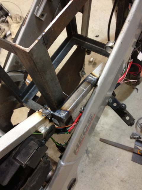
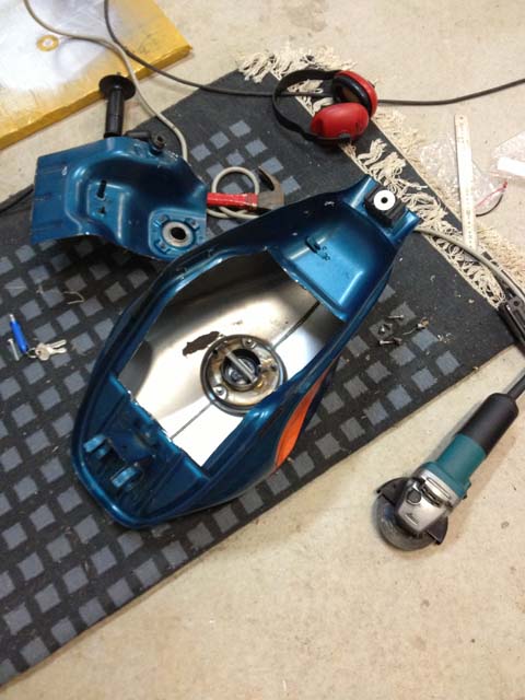
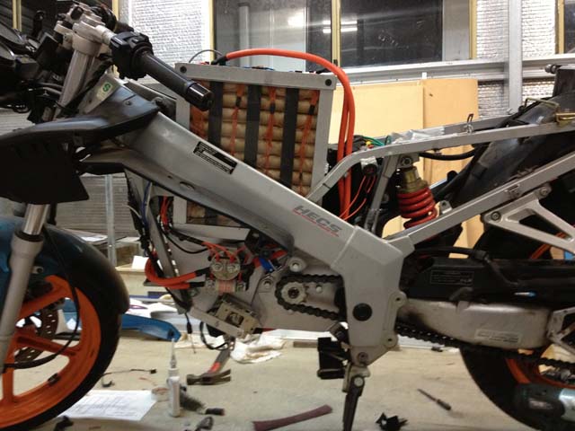
DrivetrainThe motor I chose to use is the Motenergy ME1003. Motenergy (previously Mars Electric) have been making this kind of motor for years, but the ME1003 is a recent release with higher performance than previous models. It’s a brushed DC motor rated at 72V nominal and 200A continuous, or 400A for 1 minute. Before buying any parts, it is wise to calculate theoretical performance to make sure it will meet expectations. The 62cm diameter rear wheel would do about 850rpm at 100km/h. At 72V the motor is expected to spin at 2800rpm under rated load, so for the bike to achieve 100km/h, a drive ratio of 3.3:1 would be required. The bike has a rear sprocket with 40 teeth, which I preferred to retain to minimise re-engineering. To achieve a drive ratio around 3.3:1 I opted for a 12-tooth front sprocket, which is a little smaller than the original 15-tooth. I planned to use one of my MC600C motor controllers with a 600A maximum motor current rating. At 600A the ME1003 should deliver about 100Nm of torque (based on extrapolating the dyno chart from Motenergy). Through the 3.3:1 drive ratio, the rear wheel would see 330Nm torque. With a 62cm diameter, this meant about 1000Nm (about 100kg) of acceleration force, or about 0.5Gs assuming a total bike + rider weight of 200kg. This seemed like plenty for a commuter bike, validating the suitability of the 3.3:1 drive ratio. To make sure the motor would fit before purchasing it, I made a mockup out of wood and cardboard. It fit neatly with its output shaft not far from where the original gearbox output would have been. The motor gets mounted to a 3mm thick steel plate, which is fastened to the chassis in three points (two of them being the sturdy mounts the petrol engine was previously attached to). The plate would also be later used for mounting many other components - the contactor, fuse, potbox and current sensor on the left side, and the motor controller on the right - plus have a couple of mounting points for the battery box above it. The 12-tooth drive sprocket is attached to the motor by welding it to an off-the-shelf 7/8” bore boss with 3/16” keyway, matching the motor output shaft. The old chain was slightly too short for the new sprocket position so I purchased a new chain and cut it to length. (This is done by grinding the end off the appropriate pin and using a chain breaker tool to push the pin through, then fit the joiner link to the new end.) Battery PackAlthough the motor is only rated at 72V, I decided to use one of my MC600C controllers in the bike (in accordance with the "eat your own dog food" principle!) which can handle up to 150V and deliver 600A to the motor. The motor is rated to 400A for 1 minute, so 600A should be no problem in brief spurts. Higher voltage would also allow the motor to spin up higher than its rated 2800rpm, allowing speeds above 100km/h with the 3.3:1 drive ratio. I had several hundred K2 26650EV cells sitting in the workshop from a cancelled project, so decided to use these in the motorbike. It is fairly troublesome building a pack from so many small cells, but on the up-side these K2 cells have very high energy density - taking up about 30% less space than most LiFePO4 cells - which is quite valuable in a motorbike. The pack is assembled by spot-welding nickel strips between cells. (Click here for more information about the spot welder.) The most convenient location for the battery box was between the chassis rails, above the motor, and extending into the area occupied by the fuel tank. I was planning to run about a 96V pack, but couldn’t come up with a cell layout which would use the available space efficiently. In the end I settled on a higher voltage, lower amp-hour pack, built from 264 cells in 44-series, 6-parallel layout for a total of 140V 19.2Ah, or around 2.7kWh capacity. It is a pretty small pack so won’t give the bike much range - maybe 40kms at city speeds, and less still at highway speed. I built a cardboard mockup of the expected size of this battery pack to ensure it would fit in the available space before starting assembly. The cells were assembled in four “sheets” of 11x6 cells, stacked together with polycarbonate insulators between. The pack has per-cell voltage monitoring via fly-leads to the BMS modules mounted on a polycarbonate panel on the top. I estimate the battery will only be good for about 100A continuous, so I'll start by programming the motor controller with a 100A battery limit and see how it performs. (The motor controller can still deliver the full 600A to the motor at low speeds since controllers step up current when they step down voltage, akin to how a buck converter works.) The outer frame for the battery pack is made from welded 25x25x3mm steel right-angle, sprayed with zinc anti-rust paint. Polycarbonate sheeting between the steel and batteries acts as insulation and weather protection. (As well as a good insulator, polycarbonate has high impact resistance, is flame retardant - and looks nice!) The battery unfortunately ended up not quite fitting where I had hoped, so I had to re-route a small section of square tubing. (Not a structurally significant part of the bike luckily.) After making very sure that there was zero petrol left in the fuel tank, I cut a hole in its underside where the battery box would extend into it. Electrics
|
|||||||||||||||||||||||||||||||||||||||||||||||||||||||||||||||||||||||||||||||||
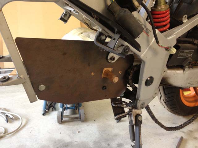

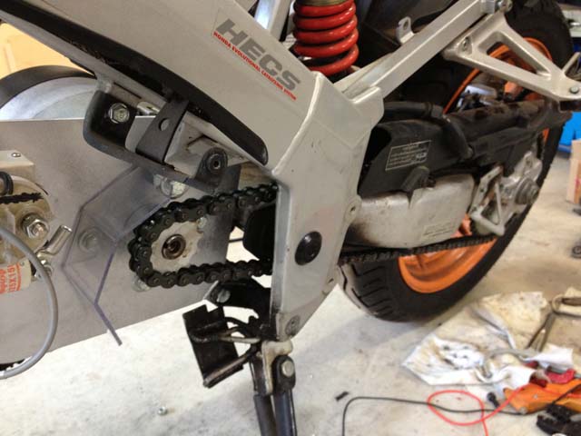
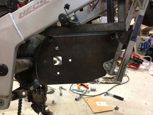
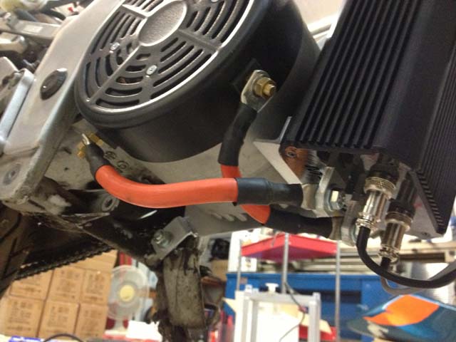
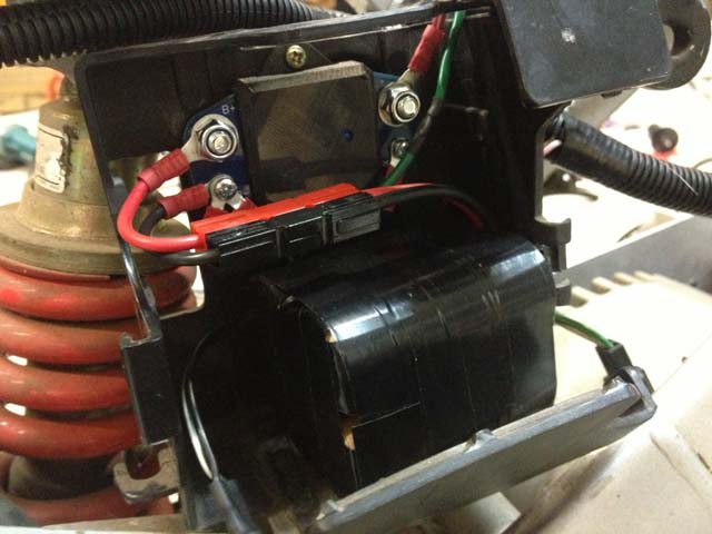
The contactor, fuse and potbox are mounted on the front left side of the motor mounting plate. The smaller orange wires you can see below go up to the EVMS Core for voltage monitoring and controller precharging. There is a polycarbonate splash guard between the chain/sprocket and these components to stop the chain throwing oil on them. Also in this area is the blue current sensor which the EVMS uses for current measurement and battery state-of-charge calculation.

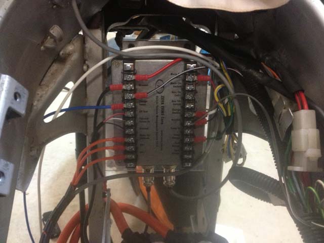
The DC/DC converter is mounted in the space just behind the battery box. The 12V battery is nearby in the original box, but is instead a small lithium battery assembled from four 26650EV cells in series (12.8V 3.2Ah). Since it’s so small and the bike may be ridden infrequently, I also installed a 12V Low Voltage Cutoff to protect the battery from over-discharge.
For the charger, I had hoped to fit a small charger somewhere on the bike. A few amps would have been fine for an overnight charge. Unfortunately nobody seems to make small 144V chargers, so I ended up with a 2kW Elcon/TC charger from EV Works. It was more expensive than I’d hoped the charger would be, and it’s much too big to fit anywhere on the bike, but the 90-minute charge time could be useful for opportunity charging. (I’ll just have to take the charger with me in a backpack if I need it!)
Performance and first impressions
The bike is a lot of fun to ride, with similar overall performance to the original, but much easier to control and more responsive thanks to the instant torque of the electric motor. I’m yet to range test it but I suspect with its small 2.7kWh battery pack, it’ll only manage about 40km at city speeds - and probably much less at highway speed.
A couple of small problems have cropped up so far:
- There’s a bit of disconcerting chain rattle while coasting, which may have existed before conversion but masked by the noise of the engine. It's still something I’d like to sort out. A chain tensioner/idler might be a solution.
- The Chennic DC/DC “backfeeds” from the battery when it’s off, draining it quite quickly (e.g overnight) - exascerbated by the tiny 3.2Ah 12V battery I’m using. The battery is protected from damage thanks to the Low Voltage Cutoff, but has minimal charge remaining. Furthermore the Chennic DC/DC seems to take several seconds to start running, which leaves the tiny, nearly flat battery to get things going by itself. Since the headlights on the bike are permanently on, the little battery's voltage sags too much during those first few seconds which causes the EVMS to generate an error, and the motor controller to trip out with a low voltage warning. The best solution might be to add a master switch on the 12V battery to isolate it completely whenever the bike is off, and/or a one way diode on the DC/DC's output to prevent the backfeeding.
Overall the project went well and was relatively straight forward - much easier to work on and cheaper than converting a car. The main "take away" from this project for me was realising the lack of space available in motorbike conversions - particularly finding room for a battery pack of reasonable size. A fully custom chassis like those used in production motorbikes can certainly make better use of the space between a motorbike's wheels.
[26 June 2014] Quick update: After some test riding around the suburbs (50-60km/h speed zones), I calculated the bike's efficiency at around 47Wh/km. With the 2703Wh battery pack, this means a theoretical range of 57km - more than I expected! If I were to carry the charger with me in a backpack (and had 90 minutes or more to charge at the destination), it allows a round trip range of 114km, which basically covers the entire Perth metro area. I'm pretty happy with this. I expect the range would be a lot less at highway speed though (since motorbikes have such poor aero) - I'll have to test that in the near future.
Update: 2016 Upgrades
In order to make the bike more useful and functional, in early 2016 I decided to fix some of the old shortcomings. Its main problem was the battery pack, which I'd assembled from a bunch of old K2 26650EV cells and were performing way under spec, resulting in approx 35km range - a little too short to be useful. Unfortunately the (conveniently) available space for batteries in the NSR is very small, so I wouldn't have been able to fit many Winstons / CALBs / Headways in the space. But after learning that (local EV enthusiast) Matt Lacey had a pile of surplus A123 20Ah pouch cells available, I purchased 44 cells from him to build a new pack from.
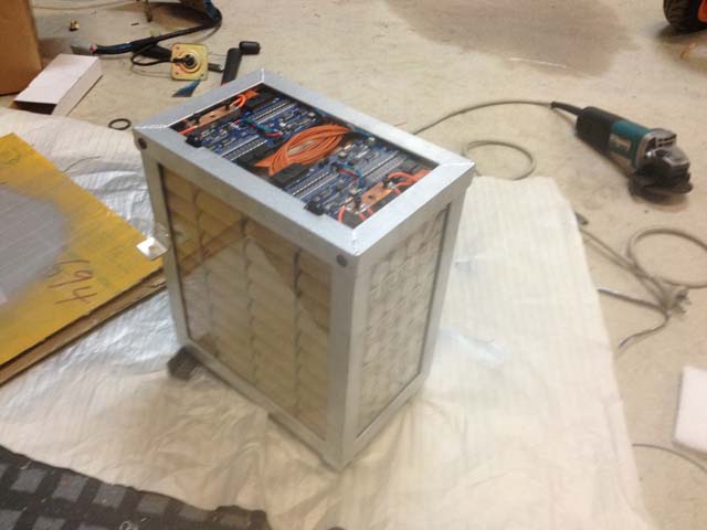
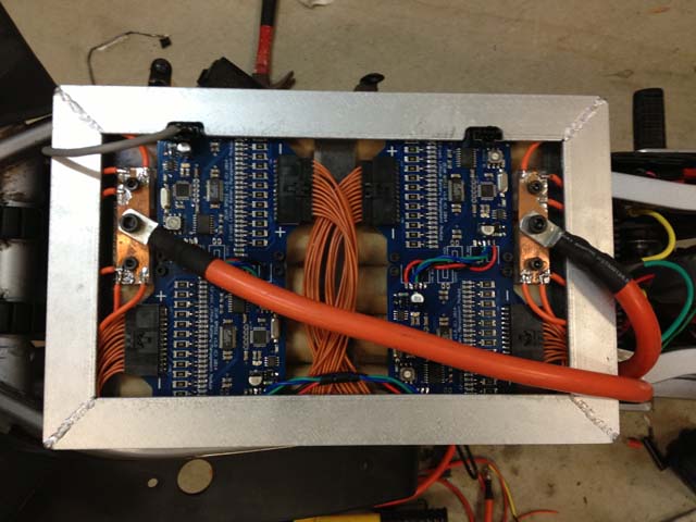
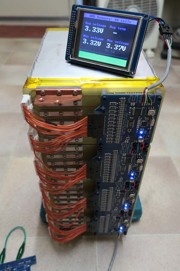
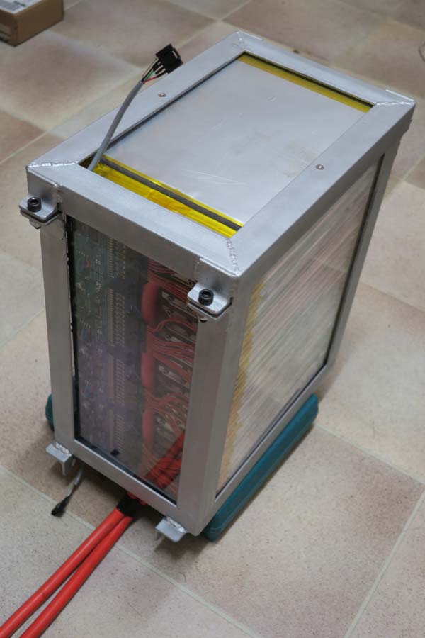
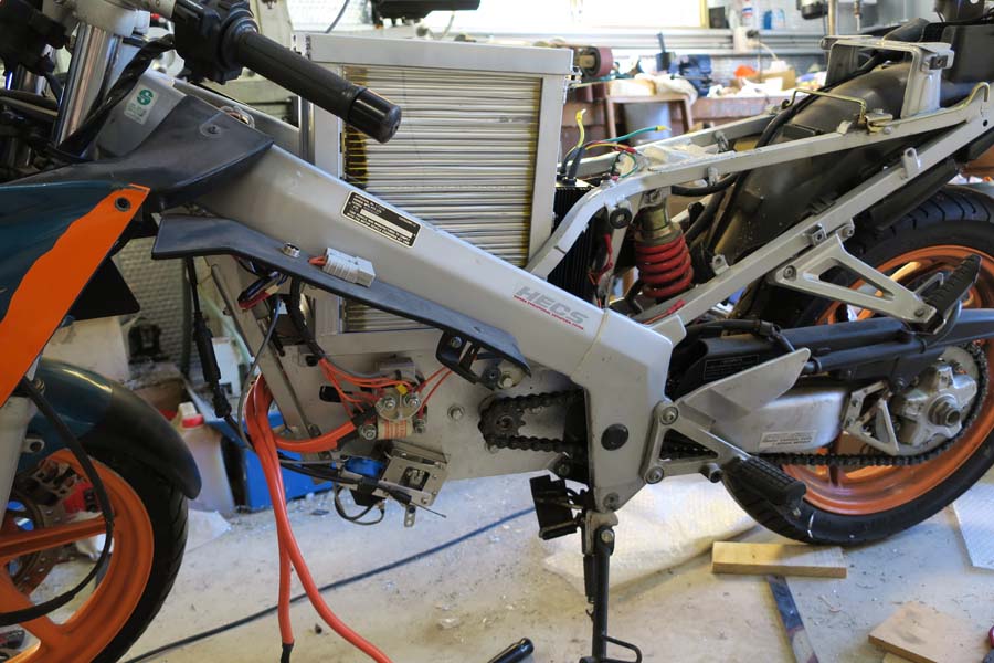
It's 44S1P, so approximately 140V 20Ah, 2.8kWh, with Agnius termination/connection kit and reusing the 4x ZEVA 12-cell BMS modules from the original pack. Enclosed in a polycarbonate-lined steel frame, with 6mm polycarbonate plates top and bottom and clamping brackets+bolts for compression. (Matt informed me they're meant to have something like 150 pounds of compression to prevent cells swelling.) It was a pretty labor-intensive little thing to build, but turned out quite well. Below are a few pics showing testing the BMS on the stack of connected cells, the complete pack in its enclosure, and installation in the bike. (Still fits under the hollowed-out fuel tank shell.)
Another shortcoming with the original build was the gear ratio of 3.3:1 being too low, making it hard on the poor little motor. So I replaced the 12-tooth motor sprocket with a 10-turn, giving it a somewhat-improved 4:1 ratio. This yields a motor speed around 2000rpm at 60km/h, which isn't too bad. After a 10km ride, the motor was about 60 degrees. Throttle response is noticeably peppier with the higher ratio too. A 5:1 or 6:1 would probably be better still, but I can't go any smaller on the motor sprocket and might have chain clearance problems with a much bigger rear sprocket.
I also finally got around to replacing the front forks, since the old ones had been slightly bent since I got the bike, which slightly compromised its handling. (Some previous owner must have had a nasty crash at some point!)

Comments
Rod Dilkes on 26th Jun 2014 | ||
Tony Castley on 1st Jul 2014 | ||
Phil on 7th Jul 2014 | |||||
| |||||
Phil on 9th Jul 2014 | ||
Steve Gates on 14th Jul 2014 | ||
Camresearch on 6th Feb 2015 | |||||
| |||||
Gavin Heywood on 11th Mar 2015 | |||||
| |||||
Zero Emission Vehicles Australia © 2026 :: Terms and Conditions, Privacy Policy, Payments and Delivery, Warranty and Returns