
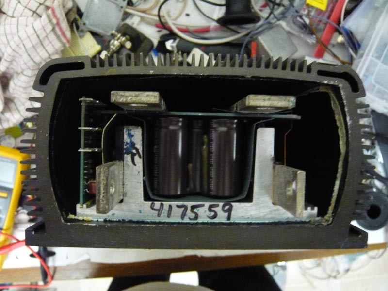
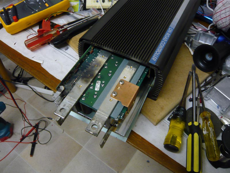
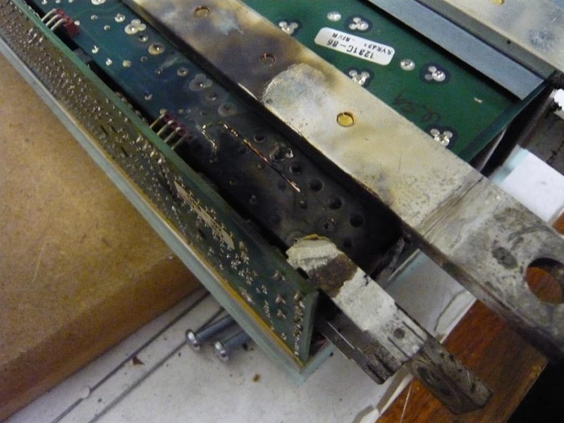
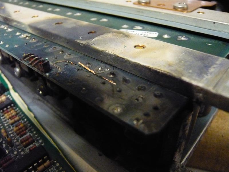
IntroductionHaving recently completed my MX5 conversion, the first problems I have been encountering are with the motor controllers. At first I had a Kelly KDH14500 installed, and while I had heard they were underpowered, let's just say that turned out to be an understatement - there's no way it would have passed licensing. So a friend kindly lent me a Curtis 1231C they had spare after upgrading to a CafeElectric Zilla controller, which he said I could use to get the vehicle licensed, until I got around to building something better. In general I would never recommend a 500A controller such as the Curtis 1231C for any direct drive applications (such as my MX5), but it did have enough power for the vehicle to keep up with traffic at least. That is, until it went pop. The first signs of its displeasure were occasional stuttering under acceleration, though I'd heard the Curtis were quirky so didn't give it too much thought. But then, about 5 minutes from home, as I was pulling up to a stop it gave a brief surge then went dead. I first checked over the power wiring thoroughly (initially suspecting that the fault might be mine) but everything looked fine. The Curtis was warm but not excessively - maybe 80 degrees. So I called a friend who brought their dino burner down and gave me a tow the rest of the way. So a fairly inauspicious first day out for the MX5, but these things are a useful learning experience if nothing else. I've since opened up the Curtis to see what the problem was, here are some pictures.. Curtis Disassembly
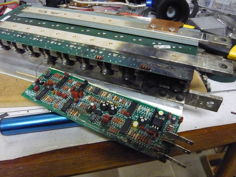
So What's Next?Many readers will have heard me complain about the Curtis 1231C previously, regarding its primitive design and excessive price, so perhaps blowing one up just proves my point.. ;) But despite this, it is still an expensive bit of gear so it'll be worth me spending some time fixing it. I certainly won't be putting it back in the MX5 again, but it's still useful for people running smaller motors. One upshot of killing the Curtis has been confirmation of the ZEVA controller's design. It's interesting to see how Curtis have designed the 1231C, but I'm now confident the ZEVA controller will be superior in many respects. Firstly, use of more modern semiconductors have allowed my design to use fewer, higher power FETs and keep them all within 80mm of the PWM source (instead of about 300mm for the Curtis). I'm also using multiple FET drivers located close to the FETs, with symmetric track lengths from the PWM generator to allow for much faster switching - hence lowering switching losses dramatically. The 1231C is using 19x IXTH50N20 MOSFETs with a 50A rating and 45mOhm on resistance. I'm using 10x IXFK120N20 MOSFETs, which have 120A rating and 16mOhm on resistance. So even with half as many FETs it'll still have 20% higher current rating and 35% lower on resistance! (i.e less power lost to heat) I'm also amazed that the 1231C's logic board is entirely analogue, made up of a dozen op amps (comparators) and hundreds of resistors! I guess it serves its purpose, but a microprocessor allows for a far simpler, tidier logic board with far more functionality. Using a micro seems like a no-brainer to me, but I guess the 1231 was designed a long time ago now. And lastly, this experience has given me a good benchmark for the ZEVA controller: If it lasts more than 2 hours in the MX5, I'll feel confident releasing it to market! Comments
|
||||||||||||||||||||||||||||||||||


Zero Emission Vehicles Australia © 2024 :: Terms and Conditions, Privacy Policy, Payments and Delivery, Warranty and Returns