|
 | Electric Trolley Speed Controller |  | Ian Hooper, 27 July 2007 | | Requirements
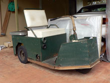
I was recently asked by our neighbours to replace the speed controller in an old electric trolley used by a local plant nursery. The existing speed controller was a system of contacts and resistors, offering just three discrete speeds, and after 20 years of use wasn't working so well anymore.
The trolley has a 24V electrical system powered by four 6V Trojan T105 deep cycle lead acid batteries. The motor is a Baldor 0.7hp (~500W) series DC type motor.
There are many off-the-shelf electronic speed controllers on the market which could have been used, but I decided it would be more interesting to design and build one myself.
|
|
 |
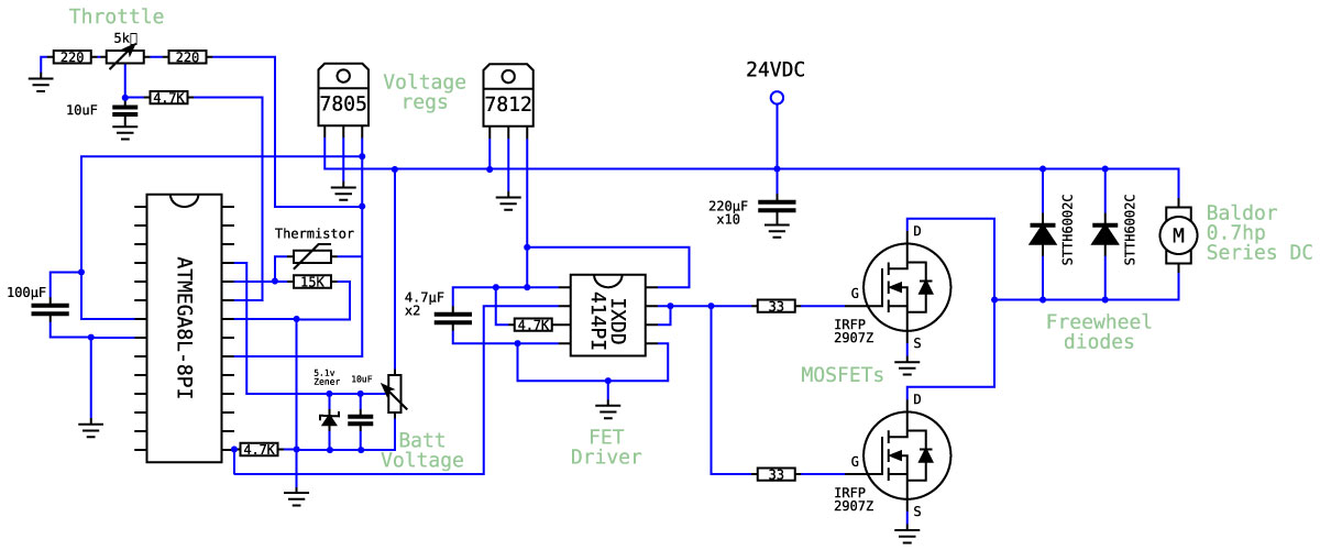
Circuit Diagram
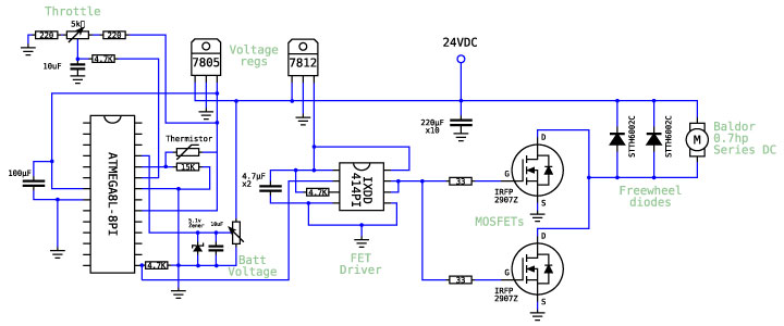
So here's the circuit diagram of the design I came up with. In short, it uses a microprocessor to control a FET driver, which switches two large MOSFETs. Ultrafast diodes are used for current freewheeling during the FET off-time, and a bank of 10 capacitors provide up to 20 amps of ripple current. For more information about how motor speed controllers work, click here.
Main Components
Atmel ATMEGA8L Microprocessor
I used this microprocessor primarily because it would do the job and they are oh-so-easy to work with. I'm using a few of its 10-bit ADC inputs for throttle, battery voltage monitoring and internal temperature sensing, and just the one PWM output signal to the FET driver. CodeVision AVR software was used to program the microprocessor.
[Click here to view the datasheet]
[Click here to view the C code] |
|
| |
|
IXYS IXDD414PI FET Driver
These are a standard DIP8 FET driver package, but offering one of the highest current ratings at 14 amps - great for running several large MOSFETs in parallel. They also have an Enable pin which can be used to gracefully shut down the FETs in a failure condition, though here I just pull the input pin low to disable output.
[Click here to view the datasheet] |
|
| |
|
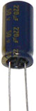
Panasonic FC-A 220uF Capacitors
These are fairly standard 50V 220uF rated capacitors, used to supply ripple current to smooth the power flow coming from the batteries. Panasonic capacitors were used due to the good value and reasonably good ripple current capabilities. These offer about 2 amps of ripple current each at 20kHz, 70°C.
[Click here to view the datasheet] |
|
| |
|
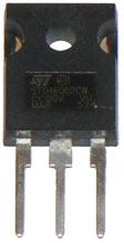
STTF6002C Ultrafast Power Diode
One of the most important features of the freewheel diode in a motor speed controller (or buck converter) is the reverse recovery time - in general, the faster the better. These ST diodes are rated to 200V, 60A and have a very fast trr of just 22 nanoseconds.
Specifications:
- Voltage rating, VRRM= 200V
- Current rating, IF(AV)= 2x 30A
- Voltage drop, VF (typ) = 0.75V
- Reverse recovery time, trr (typ) = 22ns
[Click here to view the datasheet] |
|
| |
|
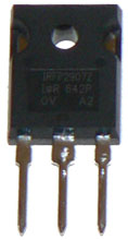
IRFP2907Z Power MOSFET
This FET was used due to the extremely low on-resistance of 4.5mΩ and a fast reverse recovery time of 41ns typical. They are available in TO-247 package (like the diodes) which is very common, allowing easy interchange with different FETs on the same board layout.
Specifications:
- Voltage, VDSS= 75V
- On resistance, RDS(ON) = 4.5 mΩ
- Max current, ID= 90A
[Click here to view the datasheet] |
|
Future improvements
One particular omission with this speed controller was current sensing and limiting. In this case the speed controller is rated to about 5x the continuous power rating of the motor, so hopefully it will never approach the limits of the power electronics. Nevertheless it would be nice to guarantee the controller could handle overcurrent situations gracefully, if it ever came up. Something for me to work on.
The same design could also be used as a controller in higher voltage systems. IXYS make a great 200V rated MOSFET, available in a 247-sized package, the IXFK120N20. They have a 17mΩ on resistance - very good for such a high voltage FET. The linear voltage regulators used would have to be the high input voltage type (which I believe are available up to 120 volts), though it may be better to use a small DC-DC converter for the logic power supply because they are much more efficient.
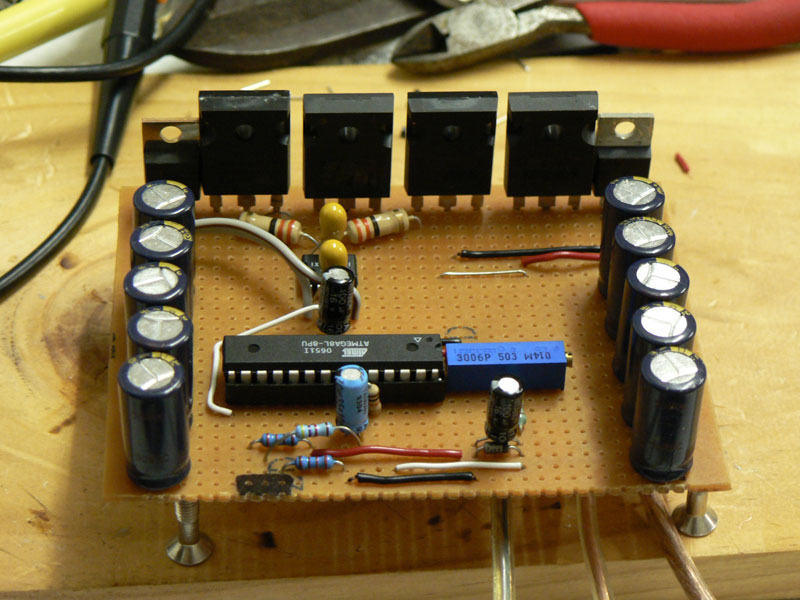
Pictures

View of the circuit board, complete minus throttle and thermistor leads |
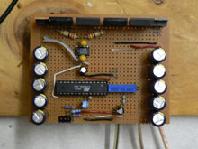
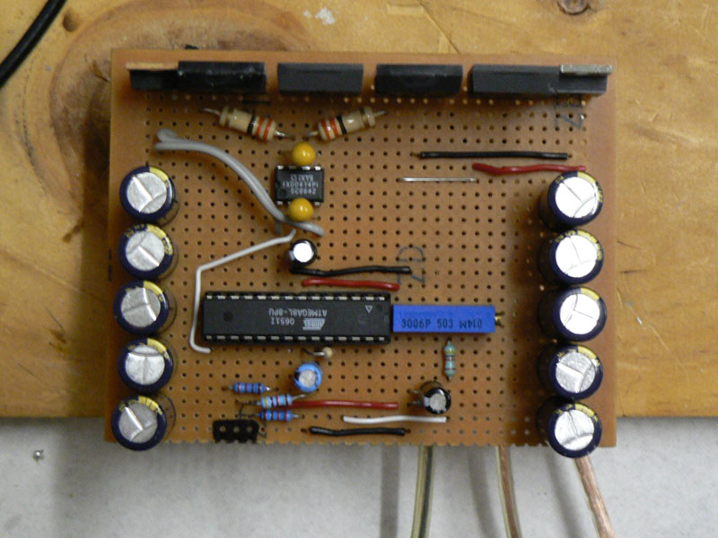
Top view of circuit board |
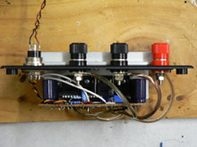
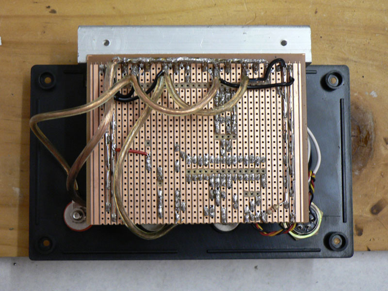
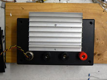
Fitted to heat sink and front panel |

Underside of circuit board. Note heavy duty wires between fets and along capacitor banks |
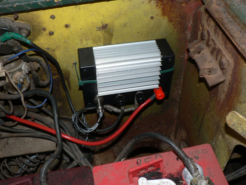
All boxed up and ready to go |
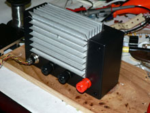
Another view of the complete unit |
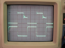
Oscilloscope trace of FET gate voltages (lower) and FET drain voltage i.e motor negative (upper) |

Installation in the electric trolley |
[FEB 09 UPDATE] Using the design for higher voltages/currents
A common question I'm asked is how the design could be modified to work with higher voltages and/or currents. The first change you'd have to make to have it work with higher voltages would be to replace the 7812 linear voltage regulator with something which will work up to your new voltage - so either a high voltage linear regulator, or an appropriate DC/DC converter with 12V output. (100mA is enough current to run the logic side.) You may also need to use higher voltage rated power devices - that is, the FETs, diodes and capacitors. Typically you should "overrate" their voltage by about a third, e.g use 100V components for a 72V controller.
Higher current capabilities can be achieved by paralleling up more FETs, diodes and capacitors. Be wary that you don't exceed the current rating of your FET driver when it has to turn many more devices on/off, and watch your physical layout e.g keep devices as close together as possible, and paths from FET driver to FET gates as short as possible!
One caveat, current limiting becomes pretty important as power levels go up. I'd highly recommend adding a current sensor (check out the Allegro or Tamura hall effect sensors), monitored by your microcontroller to avoid overcurrent and consequent damage to your power devices.
As a parting note, controller development is a reasonably steep learning curve (even if you have something to work from!) and in truth unless you're doing it for the technical challenge/enjoyment, it's usually much easier to buy a controller! The low voltage ones in particular are relatively inexpensive and usually work much more reliably than custom-made ones.
Comments| | mike perez on 13th Apr 2013
Hey Ian, I built this circuit but am having trouble with the gate driver. When the throttle is at 0 the output of the gate driver is 12v, and when the throttle is wide open, the output of the gate driver is .9v. Any idea what might be going on? Any help would be much appreciated. | | |  | | | Ian Hooper on 13th Apr 2013
Hi Mike, the first thing that comes to mind is that you could possibly have an inverting gate drive by accident? They are not uncommon. You could try applying a logic voltage directly to the gate driver input and see if it inverts, or if the inversion is being introduced before it e.g in the micro, or the throttle device. Feel free to contact me via email (ian at zeva) to discuss further! |
|
| | Jonatan Garces on 21st Jul 2013
Hi Ian, im trying to make a speed controller for a bldc motor
24 volts 150 amps , im doing my research but none of the web pages i´ve visited clear my doubts and your instructions are great, so I need help, do you know a web page , document or book that can recommend me to build the controller.
would be very grateful for any help.instructions, so I need help, do you know a web page , document or book that can recommend me to build the controller.
i would be very grateful for any help. | | | | | | Ian Hooper on 21st Jul 2013
Be prepared for a long learning curve! BLDC controllers aren't easy to get right. It will certainly help to have some grounding on how DC motor controllers work.. much of the theory is the same and a 3-ph controller is similar to three DC controllers (one per phase) with a clever control system.
Most microcontroller manufacturers have various app notes to help people with 3-phase (inc BLDC) motor control. I read a lot of these when I was learning about 3-ph motor control. For example, check out Atmel's AVR492, AVR443, AVR435, AVR495, AVR194.. Beyond that, a researcher at MIT called Shane Colton has done some interesting BLDC motor controllers and published designs on his blog, may be worth a read (but may be hard to follow if you haven't brushed up on the theory first). Good luck with your projects! |
|
| | Dhanaraj on 8th Oct 2013
It is used for 500w motor bt in case if i want to use this for 800w motor what are things i had to change??? | | | | | | Ian Hooper on 8th Oct 2013
Hi Dhanaraj, in theory the above design could handle 100A at 24V (2.4kW). You could increase the power further by running higher voltage, and/or using more MOSFETs and diodes in parallel for more current capability, but the design/layout of the power electronics becomes more important as power goes up. You may wish to have a read of the Motor Controller Design article in the Research section which talks about some of my later prototypes, going up to about 100kW in power. |
|
| | Kevin Williams on 29th Oct 2013
Hi there Ian. First off, very impressive site. It is good to see people like you trying new stuff and tinkering with technology for the greater good. I have read a lot of what you have on the site and have a a few questions. I am in the process of building an electric recumbent bike out of a 3.8 hp (2.8 kW) treadmill motor. I have the batteries and motor but I'm in need of a controller. This controller for the trolley looks like a very good starting point to something I could actually use. I am looking more in the 130 volts at 25 amp range for my use. These would be maximum values for the unit. I see your controller is only good for around 2.4 kW. In my case would it merely be swapping out the components you have for beefier stuff?
Thanks,
Kevin | | | | | | Ian Hooper on 30th Oct 2013
Hi Kevin, in some ways going higher voltage without higher amps is the easy way to increase power handling, because a single TO-257 MOSFET (and single TO-247 diode for freewheel current) can easily handle 25A. So the design could be even simpler, but with higher voltage components. I'd recommend looking at the IRFP4668 MOSFET, probably the best ~200V part out there right now. (The STTH6002C diode is already high enough voltage rated.) You'll also need higher voltage capacitors of course, perhaps 200V TS-ED Panasonics. And the final gotcha is a step-down regulator that can run off 130V.. which may be hard to find. Often it's easiest to run the logic board off some other 12V source. Good luck with your project! |
|
| | omar kandil on 31st Mar 2014
Hi Ian I'm working on a similar project but higher power I need to drive an 2300w angle grinder universal motor with similar ESC already burned many mosfet s in the progress because I am working on 240VDC using 20 12v batteries !
On of the major problems was the back emf and I think I already solved this one the second is concerning the isolation of the control circuit's power supply from the power circuit since I only need 12v for the control I also working on an ampere overload circuit to protect the igbt from failing
And also a fail safe option to stop the power once an igbt fails
I need to ask you what is the capacitors for and I need a capacitor bank and/or a parallel one with motor?
Thanks. | | | | | | Ian Hooper on 31st Mar 2014
Hi Omar, motor controller design definitely gets more difficult at higher voltages and powers. The capacitors are for supplying ripple current, they are important to negate the effect of inductance in the wires coming from the battery, in order to stop voltage spikes while switching. You want them in parallel with the batteries but as close as possible to the transistors/diodes, but NOT in parallel with the motor (because this would make the motor look a bit like a short circuit, causing big current spikes when the transistors turn on.) |
|
| | omar kandil on 1st Apr 2014
The freewheeling diode was near the motor at the back of the car and the speed control in the front under the driver seat with batteries , should I then get the speed control as near as possible to the motor and the freewheeling diode -BTW why you are using two FW diodes ?- all in the back and leave the batteries in front? (A single wire length going to the motor at the back of the car measures about 2 meters) | | | | | | Ian Hooper on 10th Apr 2014
The MOSFET(s) and freewheel diode(s) do need to be as close as possible, or inductance in the wire between them can cause voltage spikes when current conduction switches between them. The controller doesn't really need to be close to the motor, other than longer motor wires emit more EMI.
I used two freewheel diodes for higher current handling, since while the transistors are off the diodes need to conduct ("freewheel") full motor current. So in this design for 100A handling I needed 2x STTH6002 diodes for sufficient current rating. |
|
| | hanie333 on 1st Jun 2014
Hi Ian, I'm working on a project and it requires DC Motor Control so I'm in need of a controller. I want to design/build a 120VDC,1/4HP,2.8A,1800RPM DC Motor Controller. I'm still confused on what ratings of components should I use. I want to connect it to a PIC16F877A and have already programmed the PWM. How many capacitors, mosfets, freewheel diodes should I use? Any info that might help would be very much appreciated. Thank you. | | | | | | Ian Hooper on 2nd Jun 2014
Hi hanie, it sounds like your current requirement isn't very high but going to 120V can introduce other complications, and can give you an unpleasant zap so do be careful while testing! There's no fixed rules on capacitor/MOSFET/diode selection but you usually want components rated at least 30% higher than the working voltage to allow for spikes/etc, so perhaps 160V minimum in your case. If it were me I'd probably use an IRFP4668 FET, which has a much bigger current rating than needed, but they're not expensive and will run cooler than other parts. One STTH6002 diode should work fine. For capacitors, whatever is convenient but perhaps about 1000uF of 160V+ rated electrolytic caps. |
|
| | hanie333 on 17th Jun 2014
Hi,its me again. Thank you for replying my previous comment. I have another few questions and clarifications. 1st of all, when you say a minimum of 160V. Can I use IRF840 (rated 500V,8A)? It's the only power mosfet thats higher than 160V I found here in philippines. 2nd, since you advised me to use one freewheel diode. Does that mean i have to use only one power mosfet or still two like in the diagram above?. Lastly, do i have to put ten 1000uF caps? Any info that might help would be very much appreciated. Thank you very much. | | | | | | Ian Hooper on 17th Jun 2014
Hi again, IRF840 won't be great due to their high on resistance (850milliohm), meaning they'll build up a lot of heat. It would be much better to track down a FET with a lower on-resistance (e.g the IRFP4668 I mention above has about 8milliohm on resistance, so would generate literally 100x less heat than an IRF840!)
If it's your first motor controller, I'd probably recommend starting with lower voltage and power until you get the hang of it, as high voltage controllers tend to be much harder to get right safely.. |
|
| | Serik, from Kazakhstan, Almaty on 22nd Jul 2014
Hi Ian, if there any possibility to modify this controller: I need a plug braking to often reverse my future electric mini dumper? Would be it enough to place plug diode parallel to armature or I need to control U on the anode and cathode and to switch on/off the pwm?
Please , help to fix this.
Thank you. | | | | | | Ian Hooper on 23rd Jul 2014
Hi Serik, I'm not sure sorry since I have never implemented plug braking in a controller! But I think it should be OK to just have the plug braking diode connected across the armature at all times. |
|
| | Serik on 23rd Jul 2014
Thank you for replying my question. Very impressive site. Especially:
Motor Controller Design: A Photo Journal
Best regards,
Serik.
|
|